Monday, August 31, 2015

DWDM SFP Transceiver Overview

What is DWDM SFP Transceiver
Dense wavelength division multiplexing (DWDM) is a kind of wavelength division multiplexing (WDM) technology used to increase bandwidth over existing fiber optic backbones. DWDM works by combining and transmitting multiple signals simultaneously at different wavelengths on the same fiber. It increases the capacity of embedded fiber by assigning incoming optical signals to specific wavelengths with a designated wavelength band and then multiplexing the resulting signals out onto one fiber. In effect, one optical fiber is transformed into multiple virtual optical fibers. So, if you were to multiplex eight optical carriers-48 signals into one fiber, you would increase the carrying capacity of that fiber from 2.5 Gb/s to 20 Gb/s. DWDM has the ability to transport up to 80 wavelengths in what is known as the Conventional band or C band spectrum, with all 80 channels in the 1550nm region. This technology can integrate with transceiver modules especially small form-factor pluggable (SFP) modules. DWDM SFP transceiver is a hot-swappable optical module used to connect cables to switches primarily in high-capacity long-haul networks. DWDM SFP transceiver can be utilized in DWDM SONET/SDH, Gigabit Ethernet and Fibre Channel applications.

Introduction of Cisco DWDM SFP Transceiver
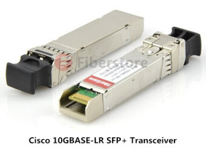
Cisco DWDM SFP transceiver is one of the most popular kinds of compact DWDM SFP transceivers used in communications for both telecommunication and data communications. The Cisco DWDM SFP module is a hot-swappable input/output device that plugs into Gigabit Ethernet SFP ports or slots of a Cisco switch or router, linking the port with the network. This module is supported across a variety of Cisco switches, routers, and optical transport devices. In the process of transmitting data, the main function of DWDM SFP transceiver is to convert electrical bits to optical pulses. It can transmit and receive multiple signals with different wavelengths at the same time, making fiber to fiber configuration possible.
    Cisco DWDM SFP

How to Install DWDM SFP Transceiver
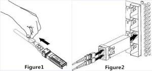
To install DWDM SFP transceiver, you are supposed to follow three steps:
Step1: Remove the DWDM SFP module from its protective packing (Do not remove the optical bore dust plug until you are directed to do so later in the procedure).
Step2: Check the label on the SFP transceiver module body to verify that user has the correct model for the network. (DWDM SFP module can be identified by its label which lists the SFP model and the wavelength).
Step3: Verify that the bale clasp on the front of the SFP module is closed before inserting the SFP module.
Step4: Align the DWDM SFP module in front of the slot opening, remove the dust plug from the SFP transceiver module optical bores and immediately slide the SFP module into the slot, and verify that whether the connect on the module snaps into place in the rear of the slot.

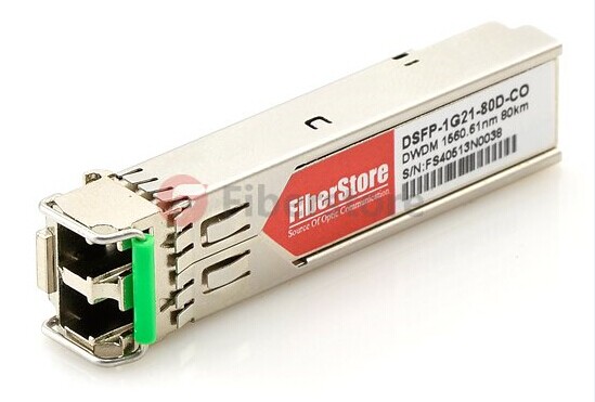
Fiberstore’s DWDM SFP transceivers provide a high-speed serial link at signaling rates from 100 Mbps to 2.5Gbps. These DWDM SFP modules meet the requirements of the IEEE802.3 Gigabit Ethernet standard and ANSI Fiber Channel specifications. We provide many types of DWDM SFP transceivers among which there is a kind designed for single mode fiber and operates at a nominal DWDM wavelength from 1530.33nm to 1561.41nm as specified by the ITU-T. For example, DWDM-SFP10G-56.55 provides a compatible data-rate of 10 Gbps with 1556.55nm for distances up to 80 km. And DWDM-SFP10G-61.41 provides a compatible data-rate from 9.9 Gbps to 11.1 Gbps with 1561.41nm for distances up to 80 km. Both of them are designed to deploy in the DWDM networking equipment in metropolitan access and core networks.

Thursday, August 20, 2015

Introduction of SFP+ Transceiver

In the 10 Gigabit Ethernet world, fiber optical transceivers have been developed along the way to meet the increasing usage and demand for higher-performance servers, storage and interconnects. XENPAK was the first MSA for 10GE and had the largest form factor. X2 and XPAK were later competing standards with smaller form factors. XFP came after X2 and XPAK. Then smaller SFP (small form-factor pluggable) enabling greater port density followed the XFP. The newest module standard is the enhanced small form-factor pluggable transceiver (SFP+), which has become the most popular socket on 10GE systems.

What Is SFP+
The small form-factor pluggable plus (SFP+) can be referred to as an enhanced version of the SFP that supports data rates up to 16 Gbit/s. The SFP+ specification was first published on May 9, 2006, and version 4.1 published on July 6, 2009. SFP+ supports 8Gbit/s Fiber Channel, 10 Gigabit Ethernet and Optical Transport Network standard OTU2. It is a popular industry format supported by many network component vendors. The SFP+ product family includes cages, connectors, and copper cable assemblies. The SFP+ transceiver modules are specified for 8Gbps/10Gbps/16Gbps Fiber Channel and 10-Gigabit Ethernet applications.

Advantages
SPF+ transceiver comes with various outstanding advantages. SFP+ covers various data rates for different communication standards like Ethernet, SONET (OC-192), SDH (STM-64) or 10G Fiber Channel and any other interfaces with a data rate up to 16 Gbps. It is with more compact size and measurement than former X2, Xenpak and XFP, which enables SFP+ suitable for installations with higher port density. In addition, SFP+ takes the advantage of lower power consumption for less than 1W, like Cisco SFP+ transceiver shown in the following picture. SFP+ transceivers are with managed digital optical monitoring and superior high temperature performance. Therefore, it is a cost effective way to connect a single network device to a wide variety of fiber cable distances and types using a SPF+ transceiver module.
Cisco 10GBASE-LR SFP+ Transceiver

Applications
SPF+ transceivers are designed to use together with small form factor connectors and offer high speed and physical compactness, providing instant fiber connectivity for your networking gear. They are available for copper and for all common fiber modes, wavelengths and data rates and allow network operators to connect different interface types to the same network equipment, via an SFP+ port. To take advantage of this flexibility and to save money, more and more network equipment are being designed with SFP/SFP+ ports. Several industrial acknowledged standards for SFP+ have been made for 10Gpbs networks, including 10Gbase-SR which defines the SFP+ transceiver working with OM3 10G multimode fiber at 30 to 300 meters range, 10Gbase-LR which defines the SFP+ transceiver working with single mode fiber at 10km range, and so on.

Fiberstore is a leading supplier of SFP+ transceivers. We have a large selection of SFP+ transceivers in stock, such us SFP+ MM 300m, SFP+ 10km, SFP+ 40km, SFP+ 80km, CWDM SFP+, DWDM SFP+, BiDi SFP+, etc. All of our SFP+ transceivers are tested in-house prior to shipping to ensure that they will arrive in perfect physical and working condition. We offer our customers with high-performance and cost-effective products to fulfill their requirements, contributing this way to the customer's success and satisfaction.


Originally published at http://www.sfp-transceiver-modules.com/wiki_list

Tuesday, August 18, 2015

100G Ethernet Fiber Optic Transceiver

With the economics-driven growth of global regional and local fiber communication network over the past few decades, 100 Gigabit Ethernet, a high-speed computer network technology was first defined by the IEEE 802.3ba-2010 standard. The recent rapid increase in the volume of communications traffic has led to a spread of 100G Ethernet for transmitting Ethernet frames at rates of 100 gigabits per second. In order to meet the data transmission needs, a high-performance and flexible implementation of 100G Ethernet - 100G optical transceiver has now started to ship into the market.

What Is 100G Transceiver 
100G transceiver is designed to offer 100 Gigabit Ethernet connectivity options for data center networking, enterprise core aggregation, and service provider transport applications. So far, a series of module form factors have been developed to support the 100Gbps Ethernet, including CFP, CXP, CFP2, CFP4, QSFP28, etc. Next, this article will give you a look at how the CFP developed during the past few years.

The Development of CFP 
When the IEEE finished the first 100G standard for Ethernet networks, the transceiver industry launched an alphabet soup of form factors. The first 100G transceivers have been based on the C form-factor pluggable (CFP) module, which is a large module capable of handling up to 24 watts of power dissipation. First-generation transceivers with multiple chips and large power requirements have used this module, which is specified by a multisource agreement. The CFP MSA defines hot-pluggable optical transceiver form factors to enable 40 Gb/s and 100 Gb/s applications. But CFP is primarily developed for 100 Gigabit Ethernet systems where the CFP modules use the 10-lane CAUI-10 electrical interface. CFP module measures 82 mm (3.22 inches) by 14 mm (0.55 inches), making it a large module that takes up a lot of space on the front panel of a switch or router. CFP MSA has defined the module factors that emphasize flexibility at the expense of its large size. The CFP transceivers are compliant with the CFP MSA, IEEE 802.3ba and OTU4 specified in ITU-T.
As the 100 Gb/s media interfaces evolve, they are becoming more efficient and being upgraded with faster internal paths for transmitting signals. The improvements in electrical signaling standards make electrical signals achieve 25 Gb/s on high-volume chip and card interfaces. Based on these new standards for electrical signaling, fewer lanes are needed, resulting in fewer connections. For that reason, a new generation of CFP - CFP2 was first demonstrated in 2012. The CFP2 optical transceivers appear to be more compact, and the size is reduced compared to CFP. The CFP2 transceivers use the 10-lane CAUI-10 electrical interface or the 4-lane CAUI-4 electrical interface. They are compliant with the CFP MSA, IEEE 802.3ba and OTU4 specified in ITU-T recommendations, and CFP2 transceivers double front panel port density compared to CFP transceivers.
The other upgraded version of CFP is CFP4 optical transceiver which was demonstrated in October 2013. CFP4 transceiver is nearly the half size of CFP2 transceiver. It achieves lower power consumption and quadruples front panel port density in comparison to CFP2 transceiver. CFP4 transceiver is compliant with the CFP4 MSA and IEEE 802.3bm by using the 4-lane CAUI-4 electrical interface.
CFP
Compared with CFP optical transceiver, the smaller CFP2 and CFP4 optical transceiver use fewer electrical connections into the switch, and thus support fewer lanes. Using fewer lanes means that each lane must signal at a higher rate, such as 25 Gb/s. These new transceiver modules are using the latest technology based on the newer OIF (Optical Internetworking Forum) signaling standards, combined with advances in circuit integration that require less power for the transceiver.

Fiberstore provides various kinds of 100G transceivers including 100G-SR10 CXP, 100G-SR10 CFP, 100G-LR4 CFP2 and so on. CFP, CFP2 and CFP4 optical transceivers will support the ultra-high bandwidth requirements of data communications and telecommunication networks that form the backbone of the internet.


Friday, August 14, 2015

How Much do You Know About DAC

With the economics-driven growth of global regional and local fiber communication network over the past few decades, there is a higher demand for cables which can provide a lower-power means for operation on a high-quality cable segment on short fiber optic links or short copper connections such as the direct attach cables (DAC) that will be described in this article.
What is DAC
A direct attach cable (DAC) is a fixed assembly that is purchased at a given length, with the connector modules permanently attached to each end of the cable. The direct attach cable is designed to use the same port as an optical transceiver, but compared with optical transceivers, the connector modules attached to the DAC leave out the expensive optical lasers and other electronic components, thus achieving significant cost savings and power savings in short reach applications.

Types of DAC
The direct attach cable can be divided into different types according to different criteria. According to the cables used, the direct attach cables include copper cable assemblies and fiber optic cable assemblies. Besides, DAC cable assemblies can also be classified into 10G SFP+ cables, 40G QSFP+ cables, and 120G CXP cables according to the data rate supported by different connector modules.

In addition, direct attach copper cable can be divided into active and passive versions. In the active direct attach copper cable, there are signal processing electronics in the modules to improve signal quality and provide a longer cable distance. Otherwise, direct attach copper cable is considered passive. However copper cable is heavy and bulky, in order to overcome the disadvantages, active optical cable (AOC) assembly is booming in the market. AOC provides more advantages, such as lighter weight, high performance, low power consumption, low interconnection loss,etc.

What’s more, we can also divide the DAC according to the number of connectors on the end of the cable. Most DAC assemblies have one connector on each end of the cable. But there is a special kind of DAC assembly which may have 3 or 4 connectors on one end of the cable. For instance, the following 40GBASE QSFP to 4x SFP+ Breakout Active Optical Cable has a single QSFP connector (SFF-8436) rated for 40-Gbps on one end and four SFP+ connectors (SFF-8431), each rated for 10-Gbps, on the other end.
40GBASE QSFP+ to 4 SFP+ Breakout Active Optical Cable
Directions for Use
A direct attach cable is used to connect one mobility access switch with another when forming a stack. Let’s take the 10G SFP+ copper connection components for example. When a SFP+ port supports a direct attach connection, all you need to do is to insert the SFP+ module on the end of the direct attach cable into the port until it latches. If we want to replace it with a direct attach fiber cable, the first step is to remove the SFP+ direct attach copper cable from the port by pulling gently on the rubber loop (see Figure1). When the port is empty, hold the SFP+ connector attached on a direct attach fiber cable by its sides and insert it into the port (see Figure2). Make sure that it clicks firmly into place.
Installation
Fiberstore provides various kinds of high speed interconnect DAC assemblies including 10G SFP+ cables, 40G QSFP+ cables, 120G CXP cables and so on. All of our direct attach cables can meet high demand to cost-effectively deliver more bandwidth, and can be customized to meet different requirements.

Tuesday, August 11, 2015

How to Choose the 40G Transceivers

With the economics-driven growth of global regional and local fiber communication network over the past few decades, the IEEE 802.3 ba 40Gb/s Ethernet standard was published in June, 2010. In order to meet the data transmission needs in the market, a high-performance and flexible implementation of the IEEE 802.32012 for 40Gbps Ethernet - 40GBase optical transceivers are developed and widely used. The 40GBase optical networking equipment transfers data at a rate of 40 gigabits per second over Ethernet. 

40GBase optical transceivers, compliant to the IEEE standards mainly include CFP and QSFP (Quad Small Form-factor Pluggable). Today, let’s mainly discuss on how to choose the 40G QSFP transceiver. As the 40-Gigabit QSFP transceivers are used to interface networking hardware to a fiber optic cable, the choice of them depends on many factors, like the media system, the connector type, transmission distance, wavelength, etc. Thus we should consider all these factors comprehensively before we choose the 40G QSFP transceivers. 
Transport Media
Choose the right transceivers according to the transport media, namely the fiber type. According to the IEEE 802.3 ba 40Gb/s Ethernet standard, there are three types of transceivers used respectively in three types of transport media: copper, single mode fiber (SMF) and multimode fiber (MMF).
● Copper: 40GBASE-CR4 is a direct attach cable segment with the QSFP+ modules attached to each end of the cable. It reaches 40 Gb/s Ethernet over four short-range twinaxial copper cables bundled as a single cable over a standard pair of G.652 single-mode fiber.
● SMF: 40GBASE-LR4 transceiver reaches 40 Gb/s Ethernet over four wavelengths carried by a singlemode fiber optic cable.
● MMF: 40GBASE-SR4 transceiver reaches 40 Gb/s Ethernet over four short-range multimode fiber optic cables. 
Connector Type
Choose the right transceivers which are compliant with the proper connectors. The connectors widely-used mainly have following types: Duplex LC connector, MPO connector, and MTP connector (a high performance MPO connector). For instance, Cisco QSFP-40GBD-SR transceiver is compliant with the Duplex LC connector, while Arista QSFP-40G-PLR4 transceiver is compliant with the MPO connector. 
Transmission Distance
When we choose the ideal transceivers, we must consider the transmission distance and the reach requirements we need in reality. The most common types of transceivers divided by its transmission distance can reach up to 100m, 150m, 300m, 400m, 1km, 2km, 10km, 40km, etc. For example, QSFP-40G-LX4 transceiver is designed to use in short transmission and supports link lengths of 100m and 150m respectively on laser-optimized OM3 and OM4 multimode fiber cables. And some others, like QSFP-40G-ER4 transceiver which supports link lengths of 40km on single-mode fiber cable is designed to use in long distance transmission. 
Wavelength
The wavelength the transceivers operate with is an important factor in choosing the proper transceivers. For instance, QSFP-40G-LX4 transceiver converts 4 inputs channels (1271nm, 1291nm,1311nm, 1331nm) of 10Gb/s electrical data to 4 CWDM optical signals, and multiplexes them into a single channel for 40Gb/s optical transmission. While some other transceivers like QSFP-40GBD-SR consists of two 20-Gbps transmit and receive channels in the 832-918 nm wavelength range.

We provide various types of 40G QSFP transceivers including single-mode and multi-mode with different channels and wavelengths. In order to achieve a fast and successful selection of the 40G QSFP transceivers, we should consider all the above-mentioned factors comprehensively.

Monday, August 3, 2015

The Difference Between CWDM and DWDM

In fiber-optic communications, wavelength-division multiplexing (WDM) is a technology which multiplexes a number of optical carrier signals onto a single optical fiber by using different wavelengths of laser light. This technique enables bidirectional communications over one strand of fiber, as well as multiplication of capacity. A WDM system uses a multiplexer at the transmitter to join various signals together, and a demultiplexer at the receiver to split them apart When dealing with optical communication system, there are two main types of WDM systems which are used to transmit the necessary data: CWDM and DWDM.
WDM operating principle
Coarse Wavelength Division Multiplexing (CWDM) is the technology of choice for cost efficiently short-haul transmission in telecoms or enterprise networks. While Dense Wavelength Division Multiplexing (DWDM) is designed for long-haul transmission where wavelengths are packed tightly together, providing a high-capacity solution in telecom networks. Generally speaking, DWDM and CWDM are based on the same concept of using multiple wavelengths of light on a single fiber, but differ in the wavelengths spacing, number of channels and the ability to amplify the multiplexed signals in the optical space.
The major difference between them is that DWDM multiplexing systems are made for longer haul transmission, by keeping the wavelengths tightly packed. They can transmit more data over a significantly larger run of cable with less interference than a comparable CWDM system. CWDM cannot travel long distances because the wavelengths are not amplified, and therefore CWDM is limited in its functionality over longer distances. Therefore, DWDM technology is one of the best choices for transporting extremely large amounts of data traffic over long distance in optical networks.
Compared with DWDM which is a more tightly packed WDM system, CWDM has larger wavelengths spacing with fewer wavelengths be transported on the same fiber. For instance, CWDM typically has 20 nm wavelengths spacing while DWDM typically has approximately 0.8 nm, hence can pack 40 plus channels compared to CWDM in the same frequency range. Thus, more channels and higher capacity can be achieved using DWDM.
CWDM and DWDM wavelengths
CWDM systems, on the other hand, use DFB lasers that are not cooled. These systems typically operate from 0 to 70°C with the laser wavelength drifting about 6 nm over this range. This wavelength drift, coupled with the variation in laser wavelength of up to ±3 nm (due to laser die manufacturing processes), yields a total wavelength variation of about ±12 nm. However, DWDM systems require larger cooled DFB lasers for a semiconductor laser wavelength drifts about 0.08 nm/°C with temperature. The use of uncooled lasers causes lower energy consumption, which has positive financial implications for systems operators. For instance, the cost of the battery is minimized with the decreasing of energy consumption, which reduces operating costs. So DWDM systems are more expensive than CWDM systems for the application of cooled lasers.
From the above analysis, we can draw a conclusion that CWDM is a cost efficient solution in short-haul transmission and DWDM is a high-capacity solution in long-haul transmission. It’s wise to choose them properly according to our special needs. Fiberstore provides various types of CWDM and DWDM products with high performance which enable the cost efficient and fast-speed optical communications.