Friday, December 14, 2018

Ethernet Cable Types Explained: All You Need To Know

An Ethernet cable or network cable is the medium for wired networks to connect the networking systems and servers together. It plays an integral role in cabling for both residential and commercial purposes. When it comes to using Ethernet cables for setting up network connections, choosing a perfect cable is always a daunting task since there are various Ethernet cables types available for different purposes. According to the bundling types of the twisted pairs, the wiring forms, and the cable speeds or bandwidths, Ethernet cable types on the market can be classified into shielded or unshielded, straight-through or crossover, Cat5/Cat5e/Cat6/Cat7/Cat8 Etherent cables respectively. How to identify the most suitable one for your needs among the diversified Ethernet cable types? This post will give you the answer.

Bundling Types in the Jacket: Shielded vs Unshielded Ethernet Cable

Shielded (STP) Ethernet cables are wrapped in a conductive shield for additional electrical isolation, then bundled in the jacket. The shielding material is used to reduce external interference and the emission at any point in the path of the cable. Unshielded (UTP) Ethernet cables without the shielding material provide much less protection against such interference and the performance is often degraded when interference or disturbance is present. STP cables are more expensive due to the shielding, which is an additional material that goes into every meter of the cable. Compared with the unshielded Ethernet cable, the shielded Ethernet cable is heavier and stiffer, making it more difficult to handle.

Wiring Forms: Crossover Cable vs Straight-through Ethernet Cable

Straight-through cable refers to an Ethernet cable with the pin assignments on each end of the cable. In other words Pin 1 connector A goes to Pin 1 on connector B, Pin 2 to Pin 2 and so on. Straight-through wired cables are most commonly used to connect a host to client.
Straight-Through-cable
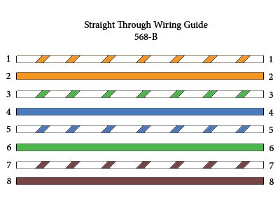
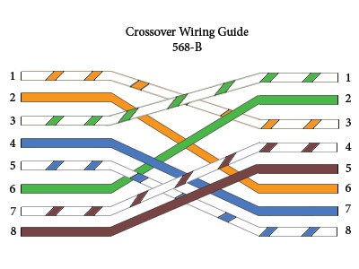
In contrast, the crossover cables are very much like straight-through cables with the exception that TX and RX lines are crossed (they are at opposite positions on either end of the cable. Using the 568-B standard as an example below you will see that Pin 1 on connector A goes to Pin 3 on connector B. Pin 2 on connector A goes to Pin 6 on connector B and so on. Crossover cables are most commonly used to connect two hosts directly.
Crossover cable

Speeds & Bandwidths: Cat5/Cat5e/Cat6/Cat6a/Cat7/Cat8 Ethernet Cable

Defined by the Electronic Industries Association, the standard Ethernet cable types can be divided into Cat5/Cat5e/Cat6/Cat6a/Cat7/Cat8 categories to support current and future network speed and bandwidth requirements.
Cat5 Ethernet Cable
Cat5 Ethernet cable introduced the 10/100 Mbps speed to the Ethernet, which means that the cables can support either 10 Mbps or 100 Mbps speeds. A 100 Mbps speed is also known as Fast Ethernet, and Cat5 cables were the first Fast Ethernet-capable cables to be introduced. Cat5 Ethernet cable can also be used for telephone signals and video, in addition to Ethernet data.
Cat5e Ethernet Cable
Cat5e Ethernet cable is an enhanced version of Cat5 cable to handle a maximum bandwidth of 100 MHz. Cat5e Ethernet cable is optimized to reduce crosstalk, or the unwanted transmission of signals between data channels. Although both Cat5 and Cat5e Ethernet cable types contain four twisted pairs of wires, Cat5 only utilizes two of these pairs for Fast Ethernet, while Cat5e uses all four, enabling Gigabit Ethernet speeds. Cat5e cables are backward-compatible with Cat5 cables, and have completely replaced Cat5 cables in new installations.
Cat6 Ethernet Cable
Cat6 Ethernet cable is certified to handle Gigabit Ethernet with a bandwidth of up to 250 MHz. It has better insulation and thinner wires, providing a higher signal-to-noise ratio. Cat6 Ethernet cables are better suited for environments in which there may be higher electromagnetic interference. Cat6 Ethernet cables can be available in both UTP and STP forms, and they are backward-compatible with both Cat5 and and Cat5e cables.
Cat6a Ethernet Cable
Cat6a Ethernet cable improves upon the basic Cat6 Ethernet cable by allowing 10 Gbps (10,000 Mbps) data transmission rates and effectively doubling the maximum bandwidth to 500 MHz. Category 6a cables are usually available in STP form, therefore they must have specialized connectors to ground the cables.
Cat7 Ethernet Cable
Cat7 Ethernet cable is a fully shielded cable that supports speeds of up to 10,000 Mbps and bandwidths of up to 600 MHz. Cat7 cables consist of a screened, shielded twisted pair (SSTP) of wires, and the layers of insulation and shielding contained within them are even more extensive than that of Cat6 cables.
Cat8 Ethernet Cable
The newly upgraded Cat8 Ethernet cable supports up to 2000MHz and speeds up to 40Gbps over 20 meters. It is fully backward compatible with all the previous categories. With inner aluminum foil wrapped around pairs and outer CCAM braid shielding, the Cat8 Ethernet cable can prevent from electromagnetic and radio frequency interference very well.

Conclusion

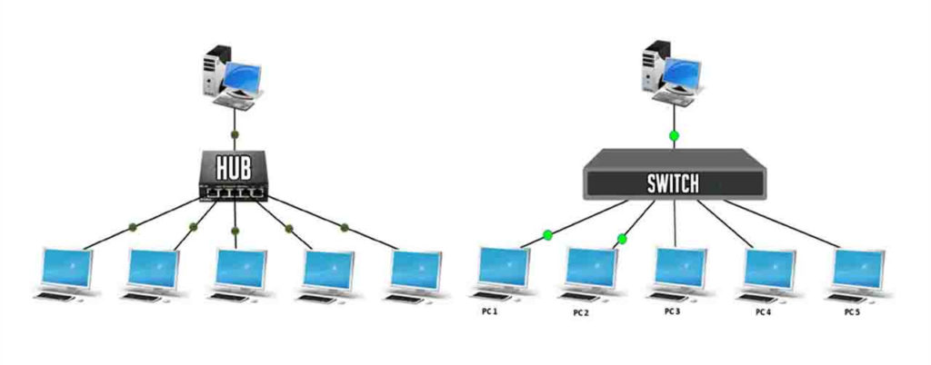
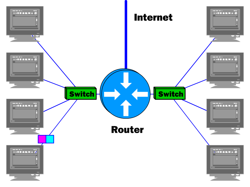
When setting up a wired connection in your home or office, you need to obtain the proper Ethernet cable types which can work with your equipment. If you are looking to connect two different devices such as computer to switch or router to hub, the straight-through cable may be the best solution. If you connect two computers together, you will need a crossover cable. The decision over UTP and STP Ethernet cable types depends on how much extent of electrical isolation is needed. When choosing among Cat5/Cat5e/Cat6/Cat7/Cat8 Ethernet cable types, it is undoubted that the more upgraded version can deliver better performance and functionality. It mainly depends on your speed and bandwidth requirement that would suit your equipment best.

Friday, November 9, 2018

Hub vs Switch vs Router: Which One Is Right for You?

Among many of today’s optical networking devices, some of the terminologies like the switch, hub and router can be quite confusing. Are they the same thing or can they be used interchangeably? Actually, each term above refers to a single device that performs a single function. In this article, we’re gonna explain the concept behind each of these terms, and give a comparison over hub vs switch vs router.
What Are Hub, Switch and Router?
A hub is a networking device that can work in conjunction with a switch or router for the whole network. A hub is a “dumb” device to broadcast whatever it hears on the input port to all the output ports. The good thing about “dumb” devices is that they don’t need a lot of configurations or maintenance. But this leads to collisions between data packets and a general degrading of network quality. If you have a hub set up between your router and the rest of your network, you’re setting yourself up for a huge headache.
Hub vs Switch
network switch is charged with the job of connecting smaller segments of a single network into a connected whole. It transfers data across a network segment using MAC addresses for reference. Data switches are extensively used in Ethernet local area networks. A data switch operates on the Data Link Layer of the OSI (Open Systems Interconnection) model. This means that data switches are fairly smarter than hubs, as they can route data on a dynamic level. If information is destined for a certain computer, the data switch will only send the data to this computer.
The router is the most complex network connection device among hub vs switch vs router. A router can direct network traffic between components on a local network and a separate network such as a wide area network or the Internet. A router also contains circuitry to determine the quickest paths for routing data. Routers use Ethernet cables to transmit and receive data and in some cases also has the capability for wireless connection to components.
Switch vs Router
Hub vs Switch
A hub looks just like a switch, but works differently. The hub is connected to other devices using Ethernet cables and any signal sent from a device to the hub is simply repeated out on all other ports connected to the hub. The method in which frames are being delivered differs between hub vs switch. For a hub, a frame is passed along or “broadcast” to every port of it. By contrast, a switch keeps a record of the MAC (Media Access Control) addresses of all the devices connected to it. Therefore, a switch can identify which system is sitting on which port. So when a frame is received, it knows exactly which port to send it to, without significantly increasing network response time.
Switch vs Router
A switch works at Layer 2 of the OSI model (there are also some Layer 3 switches that have routing capacities), which connects one point to another in a network temporarily by turning it on and off as necessary. However, a router works at Layer 3 of the OSI model, thereby it allows you to connect multiple computers to each other and also allows them to share a single Internet connection. Note that a switch only allows you to connect multiple computers into a local network.
Hub vs Router
Hubs are classified as Layer 1 devices per the OSI model, while a router is defined as Layer 3 device. The data that a hub transmits is electrical signal or bits, while a router is designed to receive data packets and determine the network point to which they should be sent in order to arrive at their appropriate destination. A hub has only one broadcast domain, while in router, every port has its own broadcast domain.
Hub vs Switch vs Router: Which One Is Right for You?
In one word, a hub glues together an Ethernet network segment; a switch connects multiple Ethernet segments more efficiently and a router can do those functions plus route TCP/IP (Transmission Control Protocol/Internet Protocol) packets between multiple LANs and/or WANs as well as much more of course.
Hub vs switch vs router: which one is right for You? For small networks where there are fewer users or devices, a hub can easily cope with the network traffic and is a cheaper option for connecting devices on a network. If more users need to be connected to a network, switches can be used in such situations to extend the number of hubs. If two or more logical subnets need to be connect together, a router would be the first option.
Source: https://community.fs.com/blog/do-you-know-the-differences-between-hubs-switches-and-routers.html

Sunday, September 16, 2018

How to Mount a Network Switch to a Rack?

A network switch has been recognized as one of the most important devices for today’s networking technology. It allows simultaneous transmission of multiple packets and partition a network more efficiently than bridges or routers. The rack mount switch can be installed in a standard 19-inch equipment rack or on a desktop or shelf. So how do you mount a network switch to a rack to establish network wiring connections? Here’s a step-by-step guide to teach you how to mount a network switch to a rack.

Preparations Before Mounting the Network Switch

Before rack mounting the switch, please pay attention to the following factors:
  • Location: The site should be at the center of all the devices you want to link and near a power outlet, so that it is accessible for installing, cabling and maintaining the devices in the rack.
  • Temperature: Since the temperature within a rack assembly may be higher than the ambient room temperature, check that the rack-environment temperature is within the specified operating temperature range (0 to 40 °C).
  • Mechanical Loading: Do not place any equipment on top of a rack-mounted unit.
  • Circuit Overloading: Be sure that the supply circuit to the rack assembly is not overloaded.
  • Grounding: The switch rack should be properly grounded.

How to Mount a Network Switch to a Rack?

Step1. Attaching the Brackets to the Switch
Attach the brackets to the network switch using the screws provided in the mounting accessory.
network switch to rack
Step2. Installing the Switch in the Rack
Mount the switch in the rack with the optional rack mount kit, usually using the rack-mounting screws. Be sure to secure the lower rack-mounting screws first to prevent the brackets being bent by the weight of the switch.
switch rack
Step3. Adding Other Switches into the Rack
If there is only one data switch to be installed in the rack, then you can make the connection to a power source now. If there are multiple switches to be mounted, you need to install the another switch on the top of the first one in the rack, and then attach the power cords.
Step4. Attaching the Power Cords
After you complete mounting all of the switches in the rack, it’s time to connect the switch rack to the power source. Remember to verify that you have the correct power supply (AC-input or DC-input and the correct wattage) for your configuration.
Caution: To prevent bodily injury when mounting or servicing the switches in a rack, you must take special precautions to ensure that the system remains stable. The following guidelines are provided to ensure your safety:
  • This network switch should be mounted at the bottom of the rack if it is the only unit in the rack.
  • When mounting the switch in a partially filled rack, load the rack from the bottom to the top with the heaviest component at the bottom of the rack.
  • If the rack is provided with stabilizing devices, install the stabilizers before mounting or servicing the switches in the rack.

Establishing Network Wiring Connections

After mounting your network switches to a rack, you can establish the network wiring connections according to your requirements now. If you’re using a Gigabit Ethernet switch, it can be connected to 10, 100 or 1000Mbps network interface cards in PCs and servers, as well as to other switches and hubs. It may also be connected to remote devices using optional SFP transceivers. No matter which type of network switches you are using, make sure that they are securely mounted in the rack and connected to the corresponding networking wiring systems.

Monday, September 10, 2018

Proper Horizontal Cable Management for Rack

Cable management is a critical part of network cabling systems that require a large number of moves, adds and changes. The improper cable management may result in cable damage or cause transmission errors and performance issues as well as system downtime. In a horizontal manager system, the cable management for rack is important in telecommunications rooms for leased office space, brokerages and trading houses where the workstations will move or add additional ports frequently. This post will analyze why the horizontal rack cable management is important and offers FS horizontal cable management solutions for rack.

Why Is Proper Horizontal Rack Cable Management Important?

  • Poorly routed cables can lead to an assortment of problems over time. Jumbled cables would increase the risk of cables to be tangled up, and a possibility of interruption when reconnecting the cables.
  • The rack cable management is directly related to hardware safety. All equipment running on the server rack is going to generate heat, so organizing a rack with a conception involving space will help promote the airflow and hardware management.
  • Cable labels in a proper horizontal rack cable management can save a lot of time on troubleshooting. Just imagine how difficult it would be to trace a cable through that mess.
  • If rack cables were unorganized, a technician would spend hours tracing wires when something goes wrong. In most circumstances, we can’t afford to stay offline while a technician unravels a tangled nest of cables. Thus a proper horizontal cable management makes it easy for the technician to identify and access where goes wrong and fix it in far less time.

Horizontal Cable Management for Rack: Where to Start with?

Horizontal cable management system is often installed within racks or cabinets to manage cables on front racks and draw cables away from equipment neatly. The rack space of a horizontal cable management infrastructure is typically 1U or 2U high. The following part gives the FS plastic & metal horizontal fiber patch panel, cable managers, lacer panels to promote a proper cable management in your horizontal network cabling systems.
Horizontal Rackmount Fiber Patch Panel
Horizontal rackmount fiber patch panels help to organize cables and eliminate cable stress for your rack enclosure cabinet. FS offers 1U 19’’ blank rackmount fiber patch panels with plastic D-rings on the cable management panel and lacing bar. These rackmount fiber patch panels can be used to organize cables for fiber optic adapters, fiber enclosures, Ethernet switches, WDM chassis, etc.
Horizontal Cable Managers with Finger Duct & Brush Strip
Horizontal cable managers with finger duct and brush strip allow neat and proper routing of the patch cables from equipment in racks and protect cables from damage. Fixed inset fingers on the front and back allow easier access to the ports for moves, adds, and changes. And the brush strip horizontal cable manager is constructed of high-quality steel with high-density nylon bristles, which can promote proper airflow through the rack and meet the demand for front-to-back cable runs.
Horizontal Lacer Panel with D-rings
Horizontal lacer panels are efficient tools for rack or enclosure cabling. These D-rings on the lacer panel are essential to avoid cable strain and prevent damage to the ports on your rack-mount equipment. The five rotating D-rings can be easily assembled or disassembled manually according to your needs.

Conclusion

This post provides users with a horizontal cable management solution that simplifies cable routing in a finished professional appearance. With proper and efficient horizontal cable management tools, cable spaghetti is not a problem anymore. You can just have a peace of mind and reap the great benefits of sound cable management. FS horizontal cable management tools provide an efficient way to manage high performance copper, fiber optic, or coaxial cables on any 1U or 2U rack. For more details, please kindly visit www.fs.com.
Originally published at http://www.fiber-optic-tutorial.com/proper-horizontal-cable-management-rack.html

Sunday, August 26, 2018

Cloud Computing vs Big Data: What Is the Relationship?

Cloud computing and big data are two of the most trending terms in the ever-lasting IT sector nowadays. You may think that they both do the same thing but actually, both of them have their own ways to work to perform. Cloud computing vs big data, what are they? What is the relationship between them?
cloud computing vs big data

Cloud Computing Tutorial

Cloud computing is a technology used to store data and information on a remote server rather than on a physical hard drive. It uses the servers hosted on the Internet to store, manage, and process data, rather than a local server or a personal computer. It means accessing resources of organization from any remote location in the world. In simple term accessing RAM, HDD, Processor of organization’s server from laptop, desktop from any of the location where Internet is available.
what is cloud computing with example
As shown in the figure above, cloud computing is collection of different services, providing services to end user via the Internet. Services like storage, virtual desktop applications, Web/App hosting process power from servers. In the following architecture, the infrastructure built to provide services is called cloud computing. This infrastructure from where the services gets accessible is front end.

Big Data Wiki

The term big data is very popular nowadays, representing huge sets of data that can be further processed to extract information. Big data carries hidden patterns and algorithms which are unlocked by using various tools available in the market. These data sets are further analyzed to provide business insights. Big data is all about storing and processing of data that is exponentially growing these days. Giants like Google, Facebook are having their own data centers to keep track and to secure their users’ data. That’s also why many big companies are equipped with reliable network equipment (including the server, router or fiber switch) for data storage or traffic forwarding in their data centers. For high performance and cost-effective enterprise routers, Gigabit Ethernet switch and 10gbe switch, FS is a case in point.
what is big data technology
Big data requires a large amount of storage space. While the price of storage continued to decline, the resources required to leverage big data can still pose financial difficulties for SMBs (small to medium sized businesses). A typical big data storage and analysis infrastructure will be based on clustered network-attached storage (NAS). Clustered NAS infrastructure requires configuration of several NAS pods with each NAS pod comprised of several storage devices connected to an NAS device. The series of NAS devices are then interconnected to allow massive sharing and searching of data.

Key Comparisons Over Cloud Computing vs Big Data

The cloud computing works in a consolidated manner, while the big data comes under the technology of cloud computing. The crucial difference between cloud computing vs big data is that cloud computing is used to handle the huge storage capacity to provide various flexible and techniques to tackle a magnificent amount of the data. While big data is the information processed with cloud computing platform. The following chart gives a more detailed comparison over cloud computing vs big data.
Cloud Computing Big Data
Basic On-demand services are provided by using integrated computer resources and systems. Extensive set of structured, unstructured, complex data forbidding the traditional processing technique to work on it.
Purpose Enable the data to be stored and processed on the remote server and accessed from any place. Organization of the large volume of data and information to the extract hidden valuable knowledge.
Working Mode Distributed computing is used to analyse the data and produce more useful data. Internet is used to provide the cloud-based services.
Benefits Low maintenance expense, centralized platform, provision for backup and recovery. Cost effective parallelism, scalable, robust.
Challenges Availability, transformation, security, charging model. Data variety, data storage, data integration, data processing, and resource management.

Cloud Computing vs Big Data: They Work Hand in Hand

Both cloud computing and big data are good at their marks. Cloud computing vs big data: they differ from each other but work hand in hand. They are the perfect combination for data storage and processing. The cloud computing has been a precursor and facilitator to the emergence of big data. If big data is the content, then cloud computing is the infrastructure.

Friday, August 17, 2018

VLAN Configuration Guidelines on Layer 3 Switch

As networks grow larger and larger, scalability becomes an issue. Every device in the network needs to send broadcasts to communicate in a broadcast domain . As more devices are added to the broadcast domain, more broadcasts start to saturate the network. In this case, VLAN (Virtual LAN) is needed to separate broadcast domains virtually, eliminating the need to create completely separate hardware LANs to overcome this large-broadcast-domain issue. In this post, we’re gonna expound the motivators to deploy VLAN and how to set up VLAN configuration step by step.
VLAN Configuration

Motivators to Implement VLAN

VLAN is a way of creating multiple virtual switches inside one physical data switch. There are a lot of reasons to implement VLAN, some of which are listed as follows.
  • Link Utilization: Link utilization is another big reason to use VLANs. Spanning tree by function builds a single path through your layer 2 network to prevent loops. If you have multiple redundant links to your aggregating devices then some of these links will go unused. To get around this you can build multiple STP topology with different VLANs.
  • Service Separation: If you have IP security cameras, IP Phones, and Desktops all connecting into the same switch it might be easier to separate these services out into their own subnet. This would also allow you to apply QoS markings to these services based on VLAN instead of some higher layer service. You can also apply ACLs on the device performing Layer 3 routing to prevent communication between VLANs that might not be desired.
  • Subnet Size: If a single site becomes too large you can break that site down into different VLANs which will reduce the number of hosts that see need to process each broadcast.

VLAN Configuration Guidelines on Layer 3 Switch

Configuring two or more VLANs to communicate with each other requires the use of either a VLAN-aware router or a Layer 3 switch. VLAN configuration can be accomplished either in CLI interface or in Web interface. The following video is a VLAN configuration example on FS S5800/S5850 10 gigabit switch.
Configure VLAN in CLI (command-line interface)
Here we take FS S5850-32S2Q Layer 3 switch as an example to configure VLAN. To create a VLAN via CLI interface, SecureCRT software is required to enter CLI interface, then perform the VLAN configuration command in the chart below:
Procedure Command Purpose
Step 1 Set the parameters of COM2 port Quick connect on startup
Step 2 #enter Enter CLI interface
Step 3 #configure terminal Enter the global configure mode
Step 4 #vlan database Enter VLAN configure mode
Step 5 #show vlan all Check the details of all VLANs on the switch
Configure VLAN in Web Interface
Configuring VLAN in Web Interface is quite simple. Just perform the following two steps and you would see the basic info of the VLAN that is created.
Step 1: Log in the Web user interface using the account and password
Step 2: Find the service management and create a new VLAN, and set its ID as 10 or 20.
Note: Ports configured to use VLAN 10 act as if they're connected to the exact same switch. Ports in VLAN 20 can not directly talk to ports in VLAN 10. They must be routed between the two or have a link that bridges the two VLANs

Summary

VLAN deployments make it easy for network engineers to partition a single switched network to match the functional and security requirements of their systems without having to run new cables or make major changes in their current network infrastructure. The proper VLAN configuration on Layer 3 switches ensures reliable and secure data link access to all hosts connected to switch ports. Knowing more about VLAN configuration would allow you to use them when you need them and to use them correctly when you do.
Source: http://www.fiber-optic-tutorial.com/vlan-configuration-guidelines-layer-3-switch.html

Monday, August 6, 2018

LAN vs WAN vs MAN: Which One to Choose?

Network is essential for establishing communications among devices such as computers, routers, or fiber switches to operate over the area they cover. LAN ((Local Area Network), WAN (Wide Area Network) and MAN (Metropolitan Area Network) are the three most prevalent types of networks that are utilized today. There are some similarities and differences between them. LAN vs WAN vs MAN, which one should you choose?
LAN vs WAN vs MAN

What Is LAN?

LAN is an interconnection of a group of related networking devices within a small geographical area where the distance between these devices is small. Some of the LANs also cover the networks in office , school, and home. Most of the LANs are built for the purpose of sharing vital resources such as printers and exchanging files.
LAN is also widely used to provide services such as sharing computer applications, gaming and accessing the internet. This type of network is under the control of one administrator who is in charge of the configurations and settings and other devices connected through Ethernet cables and wireless routers.

What Is WAN?

WAN is a kind of network connection between multiple networking devices over a large geographical area. The connection can be between different cities or even countries. A WAN network can be a collection of small networks that have been combined, or it can be as a result of various private business entities. One good example of WAN is the internet, since it connects computers from different corners of the world.
The WAN network is too complex to be managed by private administrators. Therefore, WANs usually have a public ownership, where network devices in this network can be connected either by cables or through a wireless connection.

What Is MAN?

As the name suggests, MAN is a type of network that connects network devices within a specific geographical area. MAN lies in between LAN and WAN. The area covered by MAN network is larger than that in LAN but smaller than that in WAN. MANs are mostly used to provide fast connections to cities and large institutions.
MAN experiences comparatively high speeds to facilitate fast sharing of resources such as files within a city. One main disadvantage of the MAN is the high cost. The technology deployed for MAN network is pricier than that of LAN and WAN.

Key Comparison Between LAN vs WAN vs MAN

LAN vs WAN vs MAN, there are similarities and differences between them as listed in the chart below.
ParameterLANMANWAN
Ownership of NetworkPrivatePrivate or PublicPrivate or Public
Design and MaintenanceEasyDifficultDifficult
Propagation DelayShortModerateLong
SpeedHighModerateLow
CongestionLessMoreMore
ApplicationCollege, School, HospitalSmall towns, CityCountry/Continent

Conclusion

Generally speaking, there are many advantages of LAN over MAN and WAN. LAN provides excellent reliability, high data transmission rate, and they can easily be managed. However, LAN cannot cover cities or towns and for that MAN is needed, which can connect city or a group of cities together. WAN is not restricted to a geographical location, although it might be confined within the bounds of a state or country. No matter which kind of network you choose, the routers or network switches you choose should be eligible to better satisfy your demand for network architecture. FS provides high performance gigabit PoE switch10 gigabit switch, 40 gigabit switch,etc. If you have any requirement, you can kindly visit www.fs.com.

Friday, July 20, 2018

VPLS vs MPLS: What's the Difference?

The Internet has undergone tremendous changes and broken the barriers from the impossibilities to the possibilities. To seamlessly and securely get access to the Internet or Web is what we’re seeking along the way. VPLS and MPLS are two competing technologies to direct network traffic, letting you have speedy data transfer and communication. What is a VPLS or MPLS network? What’s the difference between VPLS vs MPLS? We’re gonna to elaborate them one by one.

What Is MPLS?

MPLS (Multiprotocol Label Switching) is a type of communication that enables a service provider to provision cost effective and flexible “Virtual Private Networks” across a shared core network infrastructure. MPLS is used to send data and network traffic along the most efficient routes, which may be predetermined and are communicated using labels. Packets are carried on predetermined routes along point-to-point connections through label switch routers (LSRs) until they arrive at their destination. In MPLS network, the MPLS switch (eg. FS S5800-48F4S SFP switch) transfers data by popping off its label and sending the packet to the next switch label in the sequence. MPLS perfectly integrates the performance and traffic management capabilities of Layer 2 switching with the scalability and flexibility of Layer 3 routing.
MPLS Network

What Is VPLS?

VPLS (Virtual Private LAN Service) is a service that uses MPLS and VPN (Virtual Private Networking) to securely and seamlessly connect multiple LANs over the Internet, making them appear as if they were all on the same LAN. VPLS enables a service provider to extend a Layer 2 network across geographically dispersed sites using a shared core network infrastructure. VPLS works by creating a virtualized Ethernet switch at the provider’s edge to link remote sites. VPLS happens at Layer 2, and the carrier builds out the network, but the customer can do their own routing if they wish. This approach is ideal for corporations that have multiple data center footprints and office or remote locations that require low-latency connections between sites.
VPLS Network

VPLS vs MPLS: Factors to Consider When Choosing Them

When deciding over VPLS vs MPLS for connectivity between remote locations, there are multiple factors to consider. We’ll look into them one by one.
Switching Layer
One of the main benefits of VPLS over MPLS are the levels of security offered. As aforementioned, VPLS extend a Layer 2 network across geographically dispersed sites using a shared core network infrastructure. While MPLS perfectly integrates the performance and traffic management capabilities of Layer 2 switching with the scalability and flexibility of Layer 3 routing. VPLS does not share layer 3 routing tables with the service provider, while MPLS may do so, means that VPLS is generally the better solution for highly-sensitive data.
Network Size & Traffic
Generally, MPLS can deliver a wider type of network traffic than VPLS. VPLS is typically used for fewer locations that need very high speeds, very simple networks with high performance and high security. Thus, if you desire to connect entities such as data centers across the long-haul network backbone, VPLS is preferable as an Ethernet-based connection strategy. If a customer had hundreds of locations across the country who needs voice, data and video traffic to be carried to all locations, MPLS might make more sense because it is protocol-agnostic and can handle multiple types of traffic. MPLS may be an even clearer choice where large numbers of branches are involved.
Levels of Scalability
Another key difference between MPLS and VPLS is the inherent level of scalability. Due to the manner in which these two technologies interact with your network, MPLS is considered to be far more scalable. Using a backbone of MPLS for maximum network access and scalability, together with VPLS connections for more sensitive data often represents the best possible compromise, you would make the most of both protocols and substantially increase network efficiency.

Conclusion

Although MPLS and VPLS are different technologies, they are not mutually exclusive. Many businesses deploy both MPLS and VPLS protocols within their network in order to get the best of both worlds. FS provides gigabit ethernet switch and 10gbe switch which support both MPLS and VPLS. All these switches comes with rich L2/L3 business processing ability for core switching networks.

Sunday, July 15, 2018

VPN vs VLAN: What's the Difference?

As the popularity of the Internet has grown, many businesses are seeking for approaches to extend their own networks. First came Intranets, which are sites designed for use only by company employees. Nowadays, many of them are creating their own VPN (Virtual Private Network) or VLAN (Virtual Local Area Network) to accommodate the needs of remote employees and distant offices. What is a VPN and what is VLAN? This post will explain these two terms and the differences between VPN vs VLAN.

What Is a VPN?

A VPN is a virtual private network that utilizes a public network (usually the Internet) to connect remote sites or users together. A typical VPN network has a main local area network (LAN) at the corporate headquarters of a company, other LANs at remote offices or facilities, and individual users that connect from out in the field. Instead of using a dedicated leased line, a VPN uses "virtual" connections routed over a public or shared infrastructure such as the Internet or service provider backbone network. Therefore subscribers who are physically isolated from the main LAN can get access to the company's private network and remotely.

VPN Applicable Network Scenario
Here is a typical example of using the VPN network. As illustrated in the figure below, Network “A” sites have established a VPN (depicted by the red lines) across the service provider’s backbone network, where Network “B” is completely unaware of it’s existence. Both Network “A” and Network “B” can harmoniously coexist on the same backbone infrastructure without interrupting each other.
VPN Network

What Is a VLAN–the Subcategory of VPN

A VLAN is a group of networking devices configured to communicate on one or more LANs as if they were attached to the same wire, but actually they are located on a number of different LAN segments. VLAN networks are based on logical instead of physical connections with great flexibility. A VLAN network defines broadcast domains in a Layer 2 network. A broadcast domain is the set of all devices performed to receive broadcast frames originating from any other device within the set. Broadcast domains are usually bounded by routers since routers do not forward broadcast frames.

VLAN Applicable Network Scenario
As shown in the figure below, Layer 2 network switches are used to create multiple broadcast domains based on the configuration of these switches. Each broadcast domain is just like a distinct virtual bridge within a switch. By adding a Layer 3 router, it possible to send traffic between VLANs while still containing broadcast traffic within VLAN boundaries. The router uses IP subnets to deliver traffic between VLANs. Each VLAN has a distinct IP subnet, and there is a one-to-one correspondence of VLAN and IP subnet boundaries.
VLAN Network

VPN vs VLAN: How They Differ From Each Other?

VPN vs VLAN, they are two different concepts but related to each other. A VLAN is a subcategory of VPN, but they are designed for different hierarchies. VPN constructs range from Layer 1 to Layer 3, while VLAN is purely a layer 2 construct. A VLAN is used to group multiple computers that are not usually within the same geographical areas into the same broadcast domain. A VLAN can also segregate computers in a larger local network into smaller networks for each office or department and shielding the data so that they do not act as if they are on same network even if they are in the same switch. However, a VPN is more often related to remote access to a company’s network resources. It’s a method of creating a smaller sub network on top of an existing bigger network compared with VLAN.

Summary

No matter which one you choose over VPN vs VLAN, the foremost thing is to get reliable network switches or routers implemented in VPN or VLAN networks. FS can always fulfill your requirements by offering gigabit ethernet switch, 10gbe switch, 40gbe switches, as well as new gigabit VPN routers. They’re with powerful data-handling capacity and high compatibility for applications in data centers and enterprises.

Friday, July 6, 2018

Data Switch vs Hub in a Home Network

Data switches and hubs are common networking devices used to regenerate degraded signals and split a signal into multiple signals. They are handy for splitting up an internet connection to your home network. But do you know how they work in a home network? If they both accomplish the same thing, what’s the difference between a data switch vs hub?

What Is a Data Switch?

A data switch is charged with the job of connecting smaller segments of a single network into a connected whole. It transfers data across a network segment using MAC addresses for reference. Data switches are extensively used in Ethernet local area networks. A data switch operates on the Data Link Layer of the OSI (Open Systems Interconnection) model. This means that data switches are fairly smarter than hubs, as they can route data on a dynamic level. If information is destined for a certain computer, the data switch will only send the data to this computer. This addresses our collision problem as switches use what is called micro-segmentation, which will be elaborated later in this article.

What Is a Hub?

Hub is a network device which controls number of switches and router for the whole network. A hub is a “dumb” device in that it broadcasts whatever it hears on the input port to all the output ports. The good thing about “dumb” devices is that they don’t need much configuration or maintenance. But this leads to collisions between data packets and a general degrading of network quality. If you have a hub set up between your router and the rest of your network, you’re setting yourself up for a huge headache. A hub looks just like a switch, but works differently on the inside. You connect devices to a hub using Ethernet cable and any signal sent from a device to the hub is simply repeated out on all other ports connected to the hub.

Data Switch vs Hub in a Home Network

Data switch vs hub? How do they differ from each other? Hubs are considered Layer 1 (Physical Layer) devices whereas data switches are put into Layer 2 (Data Link Layer). This is where hubs and switches mainly differ. The Data Link layer of the OSI model deals with MAC addresses and switches look at MAC addresses when they process an incoming frame on a port.
switch vs hub
Moreover, a data switch is much smarter but pricier than a hub. A data switch can actively manage the connections between the input port and the output ports, so you won’t run into the collision problem or any of the other issues that plague hubs. As you can see below, there are multiple collision domains or segments for the switch network. If computer A and computer B sent data to each other at the same time, you would have a collision. Computer A and computer C or D, however, will not experience a collision in the process. In comparison, for a hub network, there is just one collision domain, which means that if one computer transmits data, it would be interrupted by any of the other computers in the network. Thus, the more devices you connect to the hub, the more collisions there will be in the whole network. The following figure illustrates a data switch vs hub in collision domains.
switch vs hub in collision domain

Conclusion

Data switch vs hub, which one should you choose for a home network? If you purchased the device in question within the last few years, the chance is almost zero that it’s a hub. Historically, switches were expensive and hubs were cheap, but advances in technology have made switches so cheap that they don’t even bother making hubs anymore. Thus, nowadays data switches are higher-performance alternatives to hubs in a home network. FS provides a full set of high performance data switches, including gigabit ethernet switch10gb ethernet switch, 100gbe ethernet switch, etc. If you have any requirement, please kindly visit www.fs.com.

Thursday, June 28, 2018

Do I Need a Gigabit Switch or 10/100Mbps Switch?

Ethernet network speeds have evolved significantly over time and typically range from Ethernet (802.11) at 10Mbps, Fast Ethernet (IEEE 802.3u) at 100Mbps, Gigabit Ethernet (IEEE 802.3-2008) at 1000Mbps and 10 Gigabit Ethernet (IEEE 802.3a) at 10Gbps. Meanwhile, Ethernet switches have also escalated from 10/100Mbps switch to Gigabit switch, 10GbE switch, and even 100GbE switches. The topic came up frequently that “Do I Need a Gigabit Switch or 10/100Mbps Switch?” Gigabit switch vs 10/100Mbps switch, which do I need to satisfy my network speeds requirement? This post will give you the answer.

Gigabit Switch: the Mainstream on Network Switch Market

A Gigabit switch is an Ethernet switch that connects multiple devices, such as computers, servers, or game systems, to a Local Area Network (LAN). Small business and home offices often use Gigabit switches to allow more than one device to share a broadband Internet connection. A gigabit switch operates in the same manner, only at data rates much greater than standard or Fast Ethernet. People can use these switches to quickly transfer data between devices in a network, or to download from the Internet at maximum speeds of 1000Mbps. If a switch says “Gigabit", it really means the same thing as 10/100/1000, because Gigabit switches support all three speed levels and will auto-switch to the appropriate one when something is plugged in. The following is a Gigabit 8 port poe switch with 8 x 10/100/1000Base-T RJ45 Ethernet ports.
8 port poe switch

10/100Mbps Switch: Still Alive and Well for Some Reason

10/100Mbps switch is a Fast Ethernet switch released earlier than Gigabit Ethernet switch. The data speed of 10/100Mbps switch is rated for 10 or 100Mbps. When a network switch says "10/100", it means that each port on the switch can support both 10Mbps and 100Mbps connection speeds, and will usually auto-switch depending on what's plugged into it. Currently, few devices run at 10Mbps, but it is still alive on the market for some reason. Actually, 10/100 is sufficient for internet browsing and Netflix. But if you will be doing more than one thing with your network connection, such as file transfers, or the set-top box, I would recommend you go with the Gigabit switch.
10/100Mbps Switch

Gigabit Switch vs 10/100Mbps Switch: How to Choose?

Network engineers who refresh the edge of their campus LAN encounter a fundamental choice: Stick with 100Mbps Fast Ethernet or upgrade to Gigabit Ethernet (GbE). Vendors will undoubtedly push network engineers toward pricier GbE, but network engineers need to decide for themselves which infrastructure is right for the business. Currently, Gigabit switch is much more popular than Fast Ethernet 10/100Mbps switch. Because gigabit switch used in tandem with a gigabit router will allow you to use your local network at speeds up to ten times greater than 10/100Mbps switch. If either of these component are not gigabit, the entire network will be limited to 10/100 speeds. So, in order to use the maximum amount of speed your network can pump out, you need every single component in your network (including you computers) to be gigabit compliant. In addition, by delivering more bandwidth and more robust management, Gigabit switches are also more energy efficient than 10/100Mbps switches. This offers enterprises the opportunity to lower their power consumption on the network edge.

Conclusion

There’s a multitude of switch options to choose from on the dazzling market. So, before determining the right switch for your network, you’re supposed to have a close look at your current deployment and future needs. But for most cases, we recommend you buy Gigabit Ethernet devices instead of Fast Ethernet devices, even if they cost a little bit more. FS provides a full set of Gigabit switches, including 8 port switch, 24 port switch, 48 port switch, etc. With these high performance Gigabit Ethernet switches, your local network will run faster with better internet speed.

Friday, June 22, 2018

TAP Aggregation Switch: Key to Monitor Network Traffic

For network professionals, Ethernet switches have already been used very commonly in network design. In order to ensure network security and monitor the performance of the standard Ethernet switches, network test access port (TAPs) have emerged as one of the primary sources for data monitoring or network traffic monitoring. What is network TAP or TAP aggregation switch, and how to deploy it for network traffic monitoring? This post will give you the answer.

What Is TAP Aggregation Switch or Network TAP?

A network tap is a hardware device which provides an approach to access the data flowing across a network. It functions by flow copy or aggregation, thus it’s also called TAP aggregation switch. TAP aggregation switch works by designating a device to allow the aggregation of multiple TAPs and to connect to multiple monitoring systems. In this process, all the monitoring devices are linked to specific points in the network fabric that handle the packets that need to be observed. In most cases, a third party TAP aggregation switch monitors the traffic between two points in the network. If the network between point A and B consists of a physical cable, a network TAP or TAP aggregation switch might be the best way to accomplish this monitoring. TAP aggregation switch deployed between point A and B passes all traffic through unimpeded, but it also copies that same data to its monitor port, which could enable a third party to listen.

Deployment Scenario of TAP Aggregation Switch

TAP aggregation switches or network TAPs can be extremely useful in monitoring traffic because they provide direct inline access to data that flows through the network. The following part illustrates the typical applications of TAP aggregation switches in data center and carrier network.
  • Application in Data Center
    As shown in the figure below, user can enable the timestamp and source port label function of TAP devices. The server cluster can access the exact packet process time in each data center layer via source port and timestamp message carried by the packets. From port1, port2, port3, user can distinguish the devices that the streams come from. Through T1, T2 and T3, packets forward latency of each device can be calculated, according to which users can find out the bottleneck during packet forwarding for the further optimization of data center network.
  • TAP Aggregation Switch for Data Center
  • Application in Carrier Network
    TAP aggregation switch can also be used to assist DPI (Deep Packet Inspection) in carrier networks. As illustrated below, TAP aggregation switch is applied to forward flows of carrier at internet access point and sends a mirrored copy of the packet flow to DPI device at the same time. The DPI device is for traffic analysis, once a virus on website or illegal information has been monitored, the flows will be blocked by a five elements table sent from management channel between DPI and TAP.
TAP Aggregation Switch for Carrier Network

FS TAP Aggregation Switches Solution

FS network TAPs or TAP aggregation switches deliver security, visibility and traffic analysis for high density, non-blocking 1G/10/40/100GbE networks at any scale with advanced traffic management capabilities for lossless monitoring of network traffic. They can cost-effectively and losslessly monitor all data center network traffic, while capturing and analyzing only the traffic that is needed. The table below lists FS T5800 and T8050 series TAP aggregation switches.
TAP Aggregation
Key Features
  • Standard 1U 19’’ rack mountable, 240 Gbps switching capability
  • 8x10/100/1000 Base-T Ethernet Ports, 8x1000 Base-X SFP Ports (Combo)
  • 12x10GE SFP+ Ports
  • Dual modular power supply
  • Standard 1U 19’’ rack mountable
  • 4x10GE SFP+ Ports(Combo)
  • 20x40GE QSFP+ Ports
  • 4x100GE QSFP28 Ports
  • Dual modular power supply
  • Standard 1U 19’’ rack mountable
  • 48x10GE SFP+ Ports
  • 2x40GE QSFP+ Ports
  • 4x100GE QSFP28 Ports
  • Dual modular power supply
  • Standard 1U 19’’ rack mountable
  • 48x10GE SFP+ Ports
  • 6x40GE QSFP+ Ports
  • Dual modular power supply
  • Standard 1U 19’’ rack mountable
  • 32x10GE SFP+ Ports
  • 2x40GE QSFP+ Ports
  • Dual modular power supply

Conclusion

TAP aggregation switches are crucial to any network monitoring plan because they offer an uncensored view of all network traffic. With FS TAP aggregation switches, customers can transform opaque data center traffic into comprehensive visibility for security threat detection, service availability monitoring as well as traffic recording and troubleshooting. Apart from TAP aggregation switches, the standard Ethernet switches including Gigabit switches, 10gb switches, 40gb switches and 100gb switches are also available for your choice.

Thursday, March 29, 2018

What Is SFP Connector, SFP+ Connector and SFP28 Connector?

SFP (Small Form-factor Pluggable) module connector with various data speed rate is one of the major optical transceivers used for data communication. With ever-increasing demand for faster speed and higher density, the SFP connectors have experienced several generations of update for the signal speed capability as well as port density, from the original SFP to SFP+ and then to the new SFP28 type. The compatibility of these connecting ports is the pain point for many subscribers in data communication transmission. So what’s the similarities and differences between them and are these module connectors compatible with each other when plugged into switches? SFP28 vs SFP+ vs SFP connector, which one should you choose? This paper will give you the answer.
What Is SFP Connector?
Specified by a multi-source agreement (MSA), SFP connector was first introduced in early 2000 and designed to replace the previous gigabit interface converter (GBIC) connector in fiber optic and Ethernet high-speed networking systems. Based on the IEEE 802.3, SFF-8472 protocol specification, SFP module connectors has the ability to handle up to 4.25Gb/s with greater port density than the GBIC, which is why SFP is also known as mini GBIC. This allowed it to quickly become the connector of choice for system administrators who liked the idea of being able to significantly increase their output per rack. The SFP connectors can support Gigabit Ethernet, Fibre Channel, Synchronous Optical Network (SONET) and other communication standards.
What Is SFP+ Connector?
To cater the need for faster transmission speed, the SFP+ (or SFP10) was introduced in 2006, as an extension of the SFP connector. Based on IEEE802.3ae, SFF-8431, and SFF-8432 protocol specifications, the SFP+ is designed to support data rates up to 10Gb/s. Compared with its predecessor SFP, the newly SFP+ can support Fibre Channel, 10GbE, SONET, OTN, and other communication standards. The SFP+ is similar in size to the SFP connector. And the primary difference between an SFP and a SFP+ is their transmission speed. It is noticeable that SFP/SFP+ are both copper and optical.
SFP Connector
SFP28 Connector–The Third Generation of SFP Connector
As the third generation of SFP interconnect systems, the SFP28 (Small Form-Factor Pluggable 28) is designed for 25G performance specified by the IEEE 802.3by. The SFP28 connector delivers increased bandwidth, superior impedance control with less crosstalk compared to the SFP10. SFP28 can be sorted into SFP28 SFP-25G-SR and SFP-25G-LR. The former is designed to transfer data over short distance (up to 100m over MMF) while the latter is suitable for long distance transmission (up to 10 km over SMF). Utilizing 25GbE SFP28 leads to a single-lane connection similar to existing 10GbE technology, however it can deliver 2.5 times more data, which enables network bandwidth to be cost-effectively scaled in support of next-generation server and storage solutions.
Are the SFP, SFP+ and SFP28 Products Backward Compatible?
In most cases the connector and cable assembly are all backward compatible – an SFP+ connector is a direct replacement for an SFP connector to ensure simple upgrade to customer systems. As these are standard products, the cable assembly will also be compatible between the systems – an SFP copper cable assembly can be inserted to an SFP+ cage and mate with a SFP+ connector on the board.
Then how about the new SFP28 product? Since transceivers with various SFP connector types have become an important constituent of data communication network, compatibility issue of SFP28 and SFP+ is controversial among many subscribers. Here is a typical topic from Reddit, and it says like “For a project we’re looking to purchase some nexus 93180YC-EX ToRs for 25Gb+ down to the compute nodes. Cisco states that the downlink 25Gb ports are also 10Gb capable, but one can only really assume that means that the port is compatible with SFP+ optics too. Cisco’s SFP+ compatibility matrix appears to support that claim, however just curious if any of you have any SFP28 experience yet to confirm?”
The answer is definitely “yes”. SFP28 adopts the same form factor as SFP+, just running at 25 Gb/s instead of 10Gb/s, which offers better performance and higher speed. Besides, the pinouts of SFP28 and SFP+ connectors are mating compatible. Therefore, SFP28 connector is backwards compatible with SFP+ ports. That is to say, an SFP28 can be plugged into an SFP+ port and vice versa, but plugging an SFP+ into an SFP28 port would not get you 25Gb/s data rates.
Conclusion
SFP28 vs SFP+ vs SFP connector? Have you made clear which one to choose? Whether choosing SFP or SFP+ depends on your switch types. If your switch port only supports 1G, you can only choose the 1000BASE SFP (eg.MGBSX1). If it is a 10G switch, it depends on the speed and distance you require. When choosing between SFP28 and SFP+, it all depends on the transmission data rates you need. The SFP28 aims to build 25GbE networks that enables equipment designers to significantly reduce the required number of switches and cables. Thus when considering reduced facility costs related to space, power and cooling, the SFP28 would be the optimal choice for you.
Originally published at http://www.fiber-optic-tutorial.com/sfp-connector-sfp-connector-sfp28-connector.html