Thursday, July 28, 2016

Higher Speed Transmission With Parallel Optics

Parallel optics is a term representing both a type of optical communication and the devices on either end of the link that transmit and receive information. Compared with traditional optical communication, parallel optical communication employs a different cabling structure for signal transmitting aiming at high-data transmission for short reach multimode fibers that are less than 300 meters. Traditional fiber optic transceivers cannot satisfy the increasing demand for high speed transmission, like 40GbE, while parallel optics technology can be a cost effective solution for 40/100GbE transmission.
MC2210411-SR4E
Comparison between parallel optics technology and the traditional serial optical communication would better explain what parallel optics is and the reason why it is a cost effective solution to high data rate transmission. The following of this article will offer the comparison between the two optical communication technology from two aspects: connectivity method and key components.
Connectivity Method
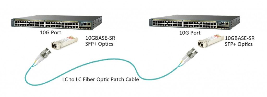
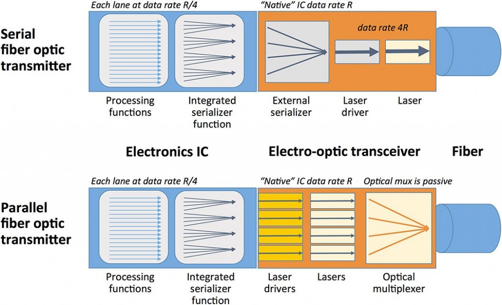
Literally, parallel optics and serial optics transmit signals in different ways. In traditional serial optical communication, on each end of the link, there are one transmitter and one receiver. For example, the transmitter on End A communicates to the receiver on End B, sending a single stream of data over a single optical fiber. And a separate fiber is connected between the transmitter on End B and the receiver on End A. In this way, a duplex channel is achieved by two fibers.
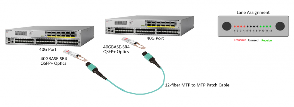
While in parallel optical communication, duplex transmission is achieved in a different way. A signal is transmitted and received through multiple paths, thus, the parallel optical communication can support higher data rate than the traditional optical communication. This is because, the devices for parallel optic communication on either end of the link contain multiple transmitters and receivers. For instance, in 2010 IEEE 802.3ba approved the 40GBASE-SR4 physical-medium-dependent multimode parallel optical solution, which uses eight fibers to transmit four duplex channels each at 10 Gigabit Ethernet. In this case, four 10Gbps transmitters on End A communicate with four 10Gbps receivers on End B, spreading a single stream of data over four optical fibers at a total data rate of 40Gbps.
Key Components
The parallel optical communication transmitting signals over multiple fibers, which has great advantages over traditional serial optical communication. It also means that it requires different components to support its high data rate transmission.
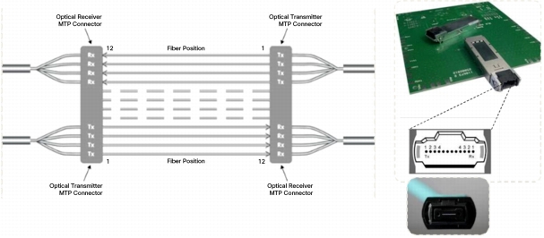
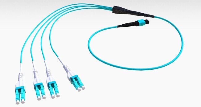
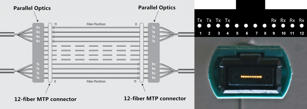
Connector — As previously mentioned, duplex transmission in serial optical communication uses 2-fiber duplex connectors, like duplex LC connectors to link the optics with other devices, while in parallel optical communication, multi-fibers are used to reach a higher data rate. Thus, multi-fiber connectors, like 12-fiber MPO connectors are used to connect with other devices. MPO connector is one key technology support parallel optical communication. This connectivity method is showed in the following picture (Tx stands for transmit; Rx stands for receive).
12-fiber-MTP-parallel-connection
Optical transceiver light source — Another complementary technology for parallel transmission is the light source of parallel optics—VCSELs (Vertical Cavity Surface Emission Lasers). Comparing with the edge-emitting semiconductor lasers in the traditional optics, VCSELs have better formed optical output which enables them to couple that energy into optical fibers more efficiently. In addition, VCSELs emit from the top surface, they may be tested while they are part of a large production batch (wafer), before they are cut into individual devices, which dramatically lowers the cost of the lasers. The following chart is about the comparison between VCSELs and edge-emitting semiconductor lasers. Cheaper to manufacture, easier to test, less electrical current required, supporting higher data rate, parallel optics using VCSELs could be a better choice to reach 40/100GbE transmission compared with traditional serial optics.
Parallel Optics for 40/100GbE Transmission
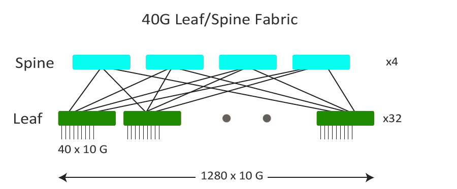
IEEE has already included physical layer specifications and management parameters for 40Gbps and 100Gbps operation over fiber optic cable. Two popular parallel optics solutions for 40Gbps and 100Gbps over multimode fibers are introduced here. For 40G, 40GBASE-SR4 transceiver is usually used, which requires a minimum of eight OM3/OM4 fibers for a transmit and receive link (4 fibers for Tx and 4 fibers for Rx). 100GBASE-SR4 transceiver (eg. QSFP-100G-SR4) is for 100Gbps transmission, which works through 4x25Gb/s 850nm VCSEL-based transmitter to achieve maximum link length of 100m on OM4 multimode fiber.
Conclusion
Parallel optical communication uses multiple paths to transmit a signal at a greater data rate than the individual electronics can support. Parallel transmission can either lower the cost of a given data rate (by using slower, less expensive optoelectronics) or enable data rates that are unattainable with traditional serial transmission. The capabilities and uses of parallel optics and MPO technology continue to evolve and take shape as higher-speed fiber optic transmission, including 40/100GbE. It is uncertain that parallel optical communication would be the trend in the future.

Tuesday, July 12, 2016

High-Speed Fiber Patch Cable Solutions from FS.COM

New technology advances in networking, such as 10G, 40G and 100G Ethernet solutions, mean that data center administrators face new challenges: maintaining high availability, reducing costs, seeking out higher efficiency and planning for future growth. Fiber optic patch cable, the key component in fiber optic communication system is designed to interconnect or cross connect fiber networks within structured cabling systems. It is used in data centers to interconnect ports and transceivers that accept LC and MPO/MTP fiber optic connectors. FS.COM offers a full range of cost-effective fiber patch cable solutions which can meet today and future growth. This article will demonstrate FS.COM high-speed fiber patch cable solutions for 10G, 40G, and 100G Ethernet transceiver ports interconnection as well as the cost-effective fiber patch cable solution for high-density patching.
10G Transceiver Interconnected Solution
Today’s data centers are still primarily architected around 10G Ethernet. After almost ten years of revolution, SFP+ gradually becomes the main stream of 10G transceiver in data center optics market. According to the optical ports of SFP+ form factor, the duplex LC patch cable is required to complete the link between two SFP+ modules which are plugged into switches, routers or server NICs (Network Interface Cards). FS.COM offers high quality standard LC duplex patch cables which are available in single-mode and multimode patch cable. With a wide range of material options, they can meet any working environment.
10G Transceiver Interconnected Solution
40G Transceiver Interconnected Solution
40G transceivers are ramping up hard as data centers deploy 40G Ethernet. QSFP+ transceivers, as the most popular form factor, are being widely used in data center switching fabrics. For the short reach interconnection between two QSFP+ ports, each QSFP+ transceiver requires an MPO/MTP connection. FS.COM offers MTP to MTP (or MPO to MPO) assemblies in multimode or single-mode version, with jacket ratings of riser, plenum and LSZH. With popular multimode OM3 and OM4 cable assemblies, users can easily upgrade to future 40/100G applications.
For single-mode 40G QSFP+ interconnection, it is commonly used with duplex LC single-mode patch cable. But for 40GBASE-PLRL4 QSFP+, a 12-fiber MPO/MTP single-mode cable is needed. As we know, a single QSFP+ port (4 x 10 Gbps) can breakout to four SFP+ port. Thus, using FS.COM MPO/MTP to LC assembliescan easily achieve the migration of 10G to 40G.
40G Transceiver Interconnected Solution
100G Transceiver Interconnected Solution
100G is considered the trend of the year of 2016. 100G transceivers including CXP, CFP, CFP2, CFP4 and QSFP28 are available for different applications. For applications requiring data rates of 100G, FS.COM provides multiple cost-effective solutions as follows:
  • CXP/CFP to CXP/CFP Interconnection
    FS.COM’s 24-fiber MPO/MTP assemblies are ideal for 100GBASE-SR10 CXP/CFP to CXP/CFP interconnection in data center, since it is implemented 10 lanes of 10 Gbps. Among the 24 fibers, only 20 fibers in the middle of the connector are used to transmit and receive at 10 Gbps and the 2 top and bottom fibers on the left and right are unused.
  • QSFP28 to QSFP28 Interconnection
    The QSFP28 is the exact same footprint as the 40G QSFP+, but is implemented with four 25Gbps lanes. To interconnect a multimode QSFP28 link, a 12-fiber MPO/MTP patch cable is required, while for single-mode link (100GBASE-LR4 QSFP28), a duplex LC single-mode patch cable is required. The interconnection of QSFP28 multimode link is similar with the case of 40GBASE-SR4 QSFP+.
  • CXP/CFP to 10 x SFP+ Interconnection
    As mentioned above, 100GBASE-SR10 CXP/CFP uses ten 10Gbps lanes to achieve 100Gbps data rate. Thus, a CXP/CFP port can be breakout to ten SFP+ ports using 24-fiber to LC harness cables from FS.COM.
High-Density Patching Solution
High-density patch cables are with higher performance and easier to use compared to common ones. FS.COM offers a wide range of high-density fiber patch cables, such as LC-HD and MPO-HD TAB fiber patch cable, Keyed LC fiber patch cables, LC uniboot fiber patch cables, bend insensitive fiber patch cables, etc. All these patch cables are with high performance and can be customized according to specific requirements.

Tuesday, June 21, 2016

Direct Uplink vs. Fan-Out Uplink

Fan-out cable or breakout cable is considered as one of the the latest enabling technologies to help increase port densities and lower costs. Taking one (large bandwidth) physical interface and breaking it out into several (smaller bandwidth) interfaces, it has been highly recommended to be used in network migration. In this post, I will compare the 40G direct uplink and the fan-out 4x10G uplink configurations and their inherent differences in maximum server scalability.
QSFP to SFP+ breakout cable
For a leaf/spine network architecture, the number of connections used for uplinks from each leaf switch determines the total number of spine switches in the design. Meanwhile, the number of ports on each spine switch determines the total number of leaf switches.
Now, imagine that we’re building a network that supports 1200 10G servers in one fabric with 2.5:1 oversubscription. The network must seamlessly expand to over 5000 10G servers without increasing latency or oversubscription in the future. Next, I will compare two different approaches.
40G Leaf/Spine Fabric – With 40G QSFP Uplink
The following picture shows us a 40G fabric to us. Each of the spine switches has 32 ports of 40G. Each leaf ToR (Top of Rack) switch is connected to the spine with 4 ports of 40G using the leaf switches 40G QSFP uplink ports. There will be 40 servers per rack connected to each leaf switch. Namely, it allows a maximum is 1280 x 10G servers at 2.5:1 oversubscription. This meets the initial scale target of 1200 servers however, it cannot scale larger. Before the network can achieve the 5000 server design goal, the 40G design will have to be re-architected.
40g-fabric
10G Leaf/Spine Fabric
As mentioned above, a direct 40G uplink is not an ideal configuration for a cost-effective server scalability. So, what level of server scalability can be achieved when using fan-out the leaf switch uplink ports with 4 x 10 G each?
The picture below shows a 10G leaf/spine fabric to us. With a QSFP+ to SFP+ optical fan-out cable, each QSFP leaf port is now fanned out to 4 x 10G interfaces each, for a total of 16 x 10G uplinks. Each of the spine switches now has 128 ports of 10G. Each leaf switch is connected to the spine with 16 ports of 10G. In this case, the maximum scale is 5120 x 10G servers at 2.5:1 oversubscription. Obviously, with the same bandwidth, latency and oversubscription, this fabric is better. It can not only be built to 1200 servers for present demand but also can seamlessly scale to over 5000 servers in the future.
10g-fabric
In conclusion, the 10G leaf/spine fabric design offers 4X greater scalability compared to the 40G fabric design with the same hardware, bandwidth, latency and oversubscription. These two configuration scenarios show us how fan-out technology are used to scale up a data center fabric. As the 10G network is widely deployed in today’s data center, the 10G direct attach cables (like Cisco SFP-H10GB-ACU10M) are preferred by many designers and companies. But higher speed demand such 40/100G is also needed. The fan-out technology not only enables new levels of server scalability, but also promotes a time-saving and cost-effective network migration.

Sunday, May 22, 2016

Next-generation Parallel Optical Data Links

Parallel-optical data links are now available and designed into many next-generation telecom/datacom central-office switches and routers. In order to meet the continued growing Internet capacity over the next couple of years, parallel-optical data links are gaining more and more popularity. This article will introduce the next-generation parallel optical data links which will play continuing role in the future network of data communications.
What Is Parallel Optical Link
Parallel optical data link is a concept opposite to serial optical data link and also a replacement for many serial data communication links. In the more typical application of parallel optic link, one byte of information is split up into bits. And each bit is coded and sent across the a single fibers. Parallel optic links are often the most cost effective for 40 Gigabit transmission, and can transmit over distances exceeding 100 meters. Serial optical solutions can relieve bandwidth-distance, cable bulk, and EMI limitations of metallic interconnects. However, they still take up significant space and they are somewhat more expensive than copper interconnects. A much less space is possible with parallel optical module (e.g. 40G-QSFP-SR4-INT) rather than with multiple serial modules. Therefore, parallel optical module greatly increases interface density. Parallel optical link modules contain laser arrays, multichannel driver, receiver ICs and fiber-ribbon optical connectors, amortizing packaging costs over several channels.
serial-vs-parallel-optical-transmitter
Key Components of Parallel Optical Links
  • Multifiber Connectors
    The connector is a critical enabling component, since its design ultimately determines the density, quality, and cost of fiber-optic interconnects. The connectors are most often used for multi-fiber links is the so-called MPO (multi-fiber push-on connector), also known by its most common vendor branded version, the MTP connector. The multifiber connectors trim costs for connector hardware, assembly, and cabling compared to single-fiber connector. This kind of connectors are not only save place for more efficient use of precious system board space, but their smaller port area also help reduce EMI. For various historical reasons, these connectors were standardized in rows of 12 fibers each, which isn’t a good match for data communication systems. Later, MPO/MTP connectors evolve to have 8-fiber row and 16-fiber row. The 40G interface is based on parallel striping of 10 Gbit/s serial channels. If we held up a standard 1 x 12 fiber MPO connector and looked back into the cable, the 4 leftmost fibers are used to transmit data, the middle 4 fibers are unused lanes, and the 4 rightmost fibers are used to receive data. Thus, we have a bidirectional interface with 4 x 10G in each direction. Following the same principle, we can use 10 Gbit/s links to build a duplex 100 Gbit/s channel, but we need an MPO connector with 2 rows of 12 fibers each. We leave the outermost fibers on either end of the rows unused, and use the remaining 10 fibers in the upper row to transmit data, and the remaining 10 fibers in the lower row to receive data.
  • Fiber Cables
    As data rates increase, link loss budgets and insertion loss will significantly decrease, so if you have plans to re-connectorize your installed fiber cable plant, be sure that the infrastructure is adequate for this application. You’ll also need adapters to fan out the MPO connection into simplex connections which are compatible with existing test and measurement equipment, to verify link performance. This kind of cables include QSFP to SFP+ breakout cable and QSFP+ to QSFP+ direct attach cable.
  • VCSEL-based Link Design
    The use of low cost VCSEL based laser transmitters is appealing for this application. While the advantages of discrete VCSELs have already placed them into serial link modules, the new parallel link modules will exploit the multichannel advantages of VCSELs arrays in parallel or WDM link modules.
Summary
Although some serial optical links can support high data rates (particularly for multi-data center connectivity or telecommunication systems), parallel optical links are a promising solution for more cost effective, higher data rate links within the data center. At shorter distances, such as within a data center rack or between adjacent racks (perhaps up to 100 meters), parallel optics are cost competitive with copper links. Thus, rather than using single-mode fiber, some laser optimized multi-mode fibers are often used. And an active optical cable allows for tradeoffs between the transmitter, receiver, and fiber parameters. We can also use existing 10 Gbit/s serial link technology and volumes by combining either 4 links to create a 40G channel, or 10 links to create a 100G channel.

Tuesday, May 10, 2016

1000Base-T SFP Module for Gigabit Ethernet

The Gigabit Ethernet technology is an extension of the 10/100-Mbps Ethernet standard. Gigabit Ethernet provides a raw data bandwidth of 1000 Mbps while maintaining full compatibility with the installed base of over 70 million Ethernet nodes. Gigabit Ethernet includes both full- and half-duplex operating modes. A Gigabit Ethernet is imperative for two reasons: faster systems and faster backbones. Gigabit Ethernet has the potential for low-cost products, freedom of choice in selecting the products, interoperability, and backward compatibility. Gigabit Ethernet supports existing applications, network operating systems, and network management; it requires a minimal learning curve for Ethernet network administrators and users. These investment preservation and risk minimization aspects are what make Gigabit Ethernet so attractive. With the development of Ethernet systems and the growing capacity of modern silicon technology, embedded communication networks are playing an increasingly important role in embedded and safety critical systems.
Gigabit Ethernet
A known type of data communication device is a small form factor pluggable (SFP) module. Typically, the SFP module plugs into an interface slot in a circuit board populated with other communication devices used in an Ethernet-based system. The SFP module includes a second serial interface,interconnected with the circuit board slot, and a first serial interface, coupled to a serial link, such as a copper or fiber link, for communicating with remote link partners. The serial link, coupled with the first serial interface, may be a 10/100/1000 Base-T copper link, or a fiber link, for example. The SFP module also offers several significant advantages over its predecessor, the GBIC (Gigabit Interface Converter), including lower cost, lower power, and smaller size. Thus, with the SFP form factor, fiber Gigabit systems may be developed featuring similar port densities as copper-only systems using RJ-45 connectors.
The SFP transceiver MultiSource Agreements (MSA) document puts forward a specification for the development of optical SFP modules based on IEEE 802.3z, the Gigabit Ethernet Standard. Specifically, the MSA calls out 1000Base-X Physical Coding Sub-layer (PCS) which supports full-duplex binary transmission at 1.25 Gbps over two copper wire-pair SerDes (Serializer/Deserializer). Transmission coding is based on the ANSI Fiber Channel 8B/10B encoding scheme.
1000Base-X makes no provision for running at slower speeds. Thus, network device ports utilizing SFPs are dedicated to operating on fiber links at speeds of 1000 Mbps. However, more than 85% of office space inside buildings is category 5 copper. Thus, ports designed to use optical SFPs can not make use of this existing cabling.
For example, a customer may require a network device, such as a router, having both optical ports for long distance connections and RJ-45 copper ports for connecting to local devices. It is often the case that not all optical ports provided on a router are needed at a given time. However, with conventional SFPs these optical ports cannot be utilized to connect with local devices connected by standard copper cabling or operating at speeds lower than 1000 Mbps. But with a 1000BASE-T copper SFP transceiver, the customer could use their existing copper cabling infrastructure instead of replacing the infrastructure. Here are two good examples of 1000BASE-T copper SFP transceivers, the Finisar FCLF-8521-3 compatible 1000BASE-T SFP copper transceiver and Cisco Linksys MGBT1 compatible 1000BASE-T SFP copper transceiver from FS.COM. Both of them are designed for 100m reach over Cat 5 UTP cable with RJ-45 interface and support max data rate of 1000Mbps.
MGBT1
The 1000BASE-T copper SFP transceiver offers a flexible and simple method to be installed into SFP MSA compliant ports at any time with no interruption of the host equipment operation. It enables for seamless integration of fiber with copper LAN connections wherever SFP interface slots can be found. Such system is economical, it saves time, offers flexibility and eliminates the necessity for replacing entire devices once the customers have to change or upgrade fiber connections and you will benefit so much from it.

Friday, May 6, 2016

QSFP+ Direct Attach Copper Cables for EX Series Switches

Quad small form-factor pluggable plus (QSFP+) direct attach copper (DAC) cables are suitable for in-rack connections between QSFP+ ports of EX Series switches. They are suitable for short distances of up to 10 meters, making them ideal for highly cost-effective networking connectivity within a rack and between adjacent racks. This article will introduce EX Series switches and QSFP+ DAC for EX Series switches.
Introduction to EX Series Switches
EX Series switches deliver scalable port densities and carrier-proven high availability features that consolidate legacy switch layers, helping to reduce capital and operational expenses and advance the economics of networking. For example, the EX 4200 series Ethernet switches with Virtual-Chassis technology, deliver the same Gigabit Ethernet (GbE) and 10GbE port densities as traditional chassis-based switches, but at one-eighth the footprint and less than one third the cost. The EX Series switches are right-sized for campus, data center and remote office environments and feature many of the same carrier-class hardware and software architectures found in core routers that were purpose-built to support the convergence of data, voice, and video onto a single always-on network.
EX 4200 Series switch
By alleviating the cost, complexity and risk associated with legacy switch infrastructures, the EX Series switches enable high-performance businesses to deploy a high-performance network infrastructure based on three key tenets – operational simplicity, carrier-class reliability, and integration and consolidation – to enable ubiquitous access to strategic assets, reduce network downtime and enhance overall security to shared assets across the extended enterprise.
Cable Specifications of QSFP+ DAC
QSFP+ direct attach copper (DAC) cable is hot-removable and hot-insertable. QSFP+ DAC mainly has two kinds. One is a cable that connects directly into two QSFP+ modules, one at each end of the cable. The cables use integrated duplex serial data links for bidirectional communication and are designed for data rates up to 40 Gbps. The other is a breakout cable consisting of a QSFP+ transceiver on one end and four SFP+ transceivers on the other end. The QSFP+ transceiver connects directly into the QSFP+ access port on the QFX Series device. The cables use high-performance integrated duplex serial data links for bidirectional communication on four links simultaneously. The SFP+ links are designed for data rates up to 10 Gbps each.
The following table describes the software support for QSFP+ passive DAC cable lengths on EX Series switches for Junos OS releases.
SWITCH
SOFTWARE SUPPORT ADDED
DAC MODEL NUMBER
EX44300 switches
Junos OS for EX Series switches, Release 13.2X51-D15 or later
EX4300 switches
  • EX4300-24T, EX4300-24P, EX4300-48T, EX4300-48T-AFI, EX4300-48P,
    EX4300-48T-DC, and EX4300-48T-DC-AF switches—Junos OS for EX Series switches, Release 13.2X50-D10 or later
  • EX4300-32F switches—Junos OS for EX Series switches, Release 13.2X51-D15 or later
  • EX4300-24T-S, EX4300-24P-S, EX4300-32F-S, EX4300-48T-S,
    and EX4300-48P-S switches—Junos OS for EX Series switches, Release 13.2X51-D26 or later
  • EX-QSFP-40GE-DAC-50CM
  • QFX-QSFP-DAC-1M
  • QFX-QSFP-DAC-3M
  • JNP-QSFP-DAC-5M
EX4550 switches
  • EX4550-32T-AFI, EX4550-32T-AFO, EX4550-32T-DC-AFI, EX4550-32T-DC-AFO,
    EX4550-32F-AFI, EX4550-32F-AFO, EX4550-32F-DC-AFI, and EX4550-32F-DC-AFO switches—Junos OS for
    EX Series switches, Release 13.2X50-D10 or later
  • EX4550-32F-S switches—Junos OS for EX Series switches, Release 12.3R5 or later
  • EX-QSFP-40GE-DAC-50CM
  • QFX-QSFP-DAC-1M
  • QFX-QSFP-DAC-3M
  • JNP-QSFP-DAC-5M
Conclusion
QSFP+ direct attach copper cables can provide cost-effective and reliable 40G speed connections for EX Series switches with distances reaching up to 10 meters. As the leading fiber optical manufacturer in China, FS.COM offers a wide selection of QSFP+ DAC with low cost but high performance. In addition, 10G SFP+ to SFP+ DAC (eg. HP JD096C), 25G SFP28 to SFP28 DAC, 40G QSFP+ to 4 XFP DAC, 100G QSFP28 to QSFP28 DAC, 100G QSFP28 to 4 SFP28 DAC are also available for your choice. All these DACs are with 100% compatibility and can be customized according to your special requirements.

Monday, May 2, 2016

QSFP+ Transceiver, AOC, DAC – Which Is You Choice?

The IEEE 802.3ba committee ratified the 40 Gigabit Ethernet standard and along with the general specification, defined a number of fiber optic interfaces. For 40GbE direct cabling between two devices using QSFP+ port, there are several options including QSFP+ transceiver option, QSFP+ DAC (Direct Attach Copper) cable, and QSFP+ AOC (Active Optical Cable). Among these options, each of them has its own merits. This article will compare them and point out which is more cost-effective for your networks.
QSFP+ Transceiver
The 40-Gigabit QSFP+ transceiver module is a hot-swappable, parallel fiber-optical module with four independent optical transmit and receive channels. These channels can terminate in another 40-Gigabit QSFP+ transceiver, or the channels can be broken out to four separate 10-Gigabit SFP+ transceivers. The QSFP+ transceiver module connects the electrical circuitry of the system with either a copper or an optical external network. The transceiver is used primarily in short reach applications in switches, routers, and data center equipment where it provides higher density than SFP+ modules.
Cables for 40 Gigabit Ethernet
Copper Cables: QSFP + to QSFP + copper cable and QSFP + to 4SFP + breakout copper cable are the two common types of QSFP + cables. QSFP + to QSFP + copper cables are hot-removable and hot-insertable. A cable consists of a cable assembly that connects directly into two QSFP + modules, one at each end of the cable. QSFP + to 4 SFP + breakout copper cable is with one QSFP + on one end and four SFP + on the other end. It allows a 40G Ethernet port to be used as four independent 10G ports thus providing increased density while permitting backward compatibility and a phased upgrade of equipment.
QFX-QSFP-DAC-1M
Fiber Cables: Active optical cable (AOC) assemblies were invented to replace copper technology in data centers and high performance computing (HPC) applications. The 40G QSFP + AOC is a parallel 40Gbps quad small form factor pluggable (QSFP +) active optical cable, which supplies higher port density and total system cost. The QSFP + optical modules provide four full-duplex independent transmit and receive channels, each are able of 10Gbps operation 40Gbps aggregate bandwidth of at least 100m multimode fiber.
Which to Choose?
Case 1: Distances Below 5 m
If the transmission distances is under 5 m, like the case that two switch ports are connected within the same rack or between racks located within the same room. The QSFP+ passive DAC cable is recommended. Take the Cisco compatible QSFP+ optics for example:
DAC5m Cisco QSFP-H40G-CU5M Compatible 40G QSFP+ Passive Direct Attach Copper CableUS$ 65.00
AOC5m Cisco QSFP-H40G-AOC5M Compatible 40G QSFP+ Active Optical CableUS$ 140.00
Transceiver & CableCisco QSFP-40G-SR4 Compatible 40GBASE-SR4 QSFP+ 850nm 150m DOM TransceiverUS$ 85.00
5M OM4 12-fiber MTP Fiber Optic Trunk Cable for 40GBASE-SR4US$ 73.00
Case 2: Distances Below 100 m (< 5 m)
For the case that transmission distance is below 100 m but beyond 5 m, the QSFP+ AOC is an ideal choice for use. In this case, the QSFP+ passive DAC cable cannot achieve such long reach requirement because of its performance limitation. While the 40GBASE-SR4 QSFP+ transceiver can do this but the cost of the MTP trunk cable is higher. Thus, here, the QSFP+ AOC is preferred.
Case 3: Distances Above 100 m
If the transmission distance is longer than 100 m, DAC cables and AOCs are usually not recommended. In this case, the 40G QSFP+ modules which are used for short-reach applications are recommended.
40G QSFP+ cables can provide inexpensive and reliable 40G speed connections using either copper cables with distances reaching up to 30ft (10 meters length) or active optical cables reaching even 300ft (100 meters). Of course, all the above are just rough estimates of the optics. In reality, more details should be included according to your specific requirements.

Tuesday, April 26, 2016

QSFP+ Interconnect Solution for 40 Gigabit Ethernet

The QSFP+ optical transceiver is the dominant transceiver form factor used for 40 Gigabit Ethernet applications. In the year of 2010, the IEEE standard 802.3ba released several 40-Gbps based solutions, including a 40GBASE-SR4 parallel optics solution for multimode fiber. Since then, several other 40G interfaces have been released, including 40GBASE-CSR4, which is similar to 40GBASE-SR4 but extends the distance capabilities.
As is know to all, two switches are connected by either transceiver modules or cables. For example, if you simply wanted to cable up two Nexus 3000s with 40GbE, the options are multi mode fiber or twinax copper. We’ll only cover the fiber throughout this post as that is where most of the questions are in recent years. So, since you are now using fiber, how do we connect these switches into the network? First, you need to insert the QSFP+ optic similar to how you would insert a fiber optic for standard 1G or 10G connectivity. For the Nexus 3000, only multi mode fiber is available, so the Cisco part number needed is QSFP-40G-CSR4. This is the equivalent of the GLC-LH-SMD or SFP-10G-SR, for 1G and 10G, respectively. The connector type for QSFP-40G-CSR4 is no longer LC, but is a MPO (multi-fiber push-on) connector.
MTP connector
It is worth noticing that cables for 40G Ethernet actually have 12 fiber strands internal to them to achieve 40GbE. Distance limitations are 100m using OM3 and 150m using OM4 fiber respectively. Because these cables are connected with MPO connectors, have 12 strands, and are ribbon cables for native 40GbE. They will not be able to leverage any of your existing fiber optic cable plant. So be prepared to home run these cable where needed throughout the data center.
However, you may not always need native 40GbE between two switches. Instead, you may opt to configure multiple 10GbE interfaces instead. In this case, the QSFP-40G-SR4 is still needed, but the cable selection is different with what was previously shown above and the ability to use current cable plants is possible. The cable required here would have an MPO connector on one end that would connect into the QSFP port and then “break out” into 4 individual fiber links on the other end. These breakout cables terminate with LC male connectors. I would like to call it MTP-LC harness cable. The application for this MTP-LC harness cable is to directly connect a QSFP+ port to (4) SFP+ ports. For most Data Center applications, the use of structured cabling is employed via MTP trunks and the use of patch panels.
MTP-LC harness cable
This is great that they terminate with LC male connectors because this allows customers to leverage the current cable infrastructure assuming existing patch panels have LC interfaces and OM3/OM4 fiber is used throughout the data center. These breakout cables are also nice if you want to attach a northbound switch that only supports 10GbE interfaces. You can easily direct connect or jump through a panel in the data center to connect the Nexus 3000 via multiple 10GbE interfaces to a Nexus 7000 (or any other switch with 10GbE-only interfaces).
Accordingly, direct attach cables which are terminated with QSFP+ connector is an alternative in 40G connectivity. For instance, HP JG331A compatible QSFP+ to 4SFP+ direct attach copper cable is terminated with one QSFP+ connector on one end and four SFP+ connector on the other end.
40G QSFP+ cables can provide inexpensive and reliable 40G speed connections using either copper cables with distances reaching up to 30ft (10 meters length) or active optical cables reaching even 300ft (100 meters). Cost of local NOC connectivity is significantly reduced by avoiding the more costly fiber transceivers and optical cables.

Thursday, April 21, 2016

Guide to High-Speed Copper Transceivers

The last few decades have seen the broad adoption of fiber optic transceivers used in optical communications for both telecommunication and data communications applications. However, would the copper connectivity withdraw from the market? Copper medium usually doesn’t require any transceivers, as they are part of the interface module. However, in order to cut down expenditures, some vendors use SFP copper transceiver with an RJ-45 female connector for Gigabit Ethernet connectivity over copper medium, or XFP copper transceiver for 10Gigabit Ethernet (10GbE) connectivity over CX4 copper. This article will give you a complete guide to these copper transceivers.
Supporting 10/100/1000 Mbps data-rate in excess of 100 meters (325 feet) reach over UTP Category5/5e cables, copper transceiver module is ideally suited for implementing small form-factor Network Interface Cards (NICs) and uplinks. As such, it is highly appropriate for use in high-density applications such as LAN 1000BASE-T, switch-to-switch interfaces, switched backplanes, blade servers, gaming devices, and router/server interfaces.
With the development of 1000BASE-T technology, 1000BASE-T and 100BASE-TX copper SFP transceiver over Category 5 copper cabling is an attractive option for network. The advantages are listed as follows:
  • For 100m reach over Cat 5 UTP cable
  • Hot-pluggable SFP footprint
  • Supports RX_LOS as link indication function
  • Fully metallic enclosure for low EMI
  • Low power dissipation (1.05 W typical)
  • Compact RJ-45 connector assembly
  • Compliant with SFP MSA and IEEE Std 802.3-2002
Here are two good examples of 1000BASE-T copper SFP transceivers, the Finisar FCLF-8521-3 compatible 1000BASE-T SFP copper transceiver and HP J8177C compatible 1000BASE-T SFP copper transceiver from FS.COM. Both of them are designed for 100m reach over Cat 5 UTP cable with RJ-45 interface and support max data rate of 1000Mbps.
FCLF-8521-3
As a kind of copper XFP transceiver, the XFP 10GBASE-CX4 module uses a CX4 connector to provide a connection to up to 15 meters over CX4 grade copper cable. Transparently to the user, the module transfers the 10GbE data stream over four full-duplex 3.125 Gbps channels over a single parallel copper cable. The product offers the ability to scale bandwidth in 10G increments, and directly with the industry standard MDI electrical socket.
XFP-10GBASE-CX4
CX4 is an extension of the four-channel 10 Gbps XAUI interface and is available in 70-pin MSA transponder modules, otherwise known as Xenpak, XPAK and X2. The 10GBASE-CX4 solution employs an Infiniband-style Twin-AX cable (click to see the Cisco 10G twinax). In this case, eight 100-ohm differential Twin-AX cables are bundled into a single outer shield. The center conductors are 24 AWG wire for compatibility with printed circuit board termination inside the connector housing. The limitation of the 10GBASE-CX4 solution is that it requires a 70-pin MSA socket and only supports the IEEE802.3ae 10GE data format.
The XFP format also offers the distinct feature of being data agnostic, which opens the market for the copper based solution to telecommunications applications as well. The 10 Gbps serial solution over copper adds the final link option to the XFP industry, offering everything from the ultra low-cost sub-20m 10 Gbps shelf-to-shelf and rack-to-rack links to 80 km or longer optical links.
Among the above-mentioned copper transceivers, what must be noticed is that copper SFP transceiver offers a flexible and simple method to be installed into SFP MSA compliant ports at any time with no interruption of the host equipment operation. It enables for seamless integration of fiber with copper LAN connections wherever SFP interface slots can be found. Such system is economical, it saves time, offers flexibility and eliminates the necessity for replacing entire devices once the customers have to change or upgrade fiber connections and you will benefit so much from it.

Monday, April 11, 2016

3 Ways Third-Party Transceivers Benefit Your Data Center

Are you still spending hundreds of dollars on the expensive optical transceiver modules for your network system in the data center? In order to cut down the costs on the expensive transceiver modules, many companies are seeking for a compatible third-party transceiver to use. For example, if your network contains Juniper routers, firewalls, and switches, you might think that only Juniper SFP branded transceivers will ensure that all of your equipment is compatible and functions optimally. However, that seemingly reasonable assumption could cost your company thousands of dollars. Compared to the third-party optical transceiver produced by third-party companies, Juniper SFP transceiver comes with dramatically inflated price tags while a third-party compatible one is roughly 80 percent less expensive than Juniper branded SFP transceiver.
What Does "Third-Party" Mean?
In commerce, a "third-party" means a supplier (or service provider) who is not directly controlled by either the seller (first party) or the customer/buyer (second party) in a business transaction. For example, in the fiber optics industry, all fiber optic transceivers are defined by Multi-Source Agreement (MSA). MSAs strictly define the operating characteristics of fiber optic networking equipment, so that system vendors may implement ports in their devices that allow MSA compliant networking components produced by different manufacturers are interoperable. As long as a manufacturer complies to MSA guidelines, their transceiver modules will function and operate identically to any other manufacturer's MSA-compliant transceivers. For instance, HP BladeSystem 455883-B21 compatible 10GBASE-SR SFP+ transceiver from FS.COM will function identically to a HP 455883-B21 transceiver and will be 100% compatible with HP networking equipment.  
455883-B21
Optical transceivers are some of the most all-around useful pieces of hardware for a network. As long as your equipment has SFP/SFP+ ports -which most do- transceivers allow you to change between a multitude of uplink types, to fit whatever wiring you have or will have in the future. They're simple, plug-and-play, and hot-swappable. Third-party optical transceivers can easily prevent thousands of dollars in new hardware costs. In spite of what's often implied by official documentation, a quality third-party optical transceiver is 100% compatible with name-brand equipment. There's simply no difference between good quality third-party transceivers and branded ones. So why choose to pay more?
Three Reasons Why Third-Party Optical Transceivers Just Make Sense
1. Low costs
The lower costs of third-party optics really cannot be overstated. Depending on the model, name brands are anywhere from 50% to 1000% more expensive than third-party alternatives. For example, you can get the Cisco QSFP-40G-CSR4 compatible 40GBASE-CSR4 QSFP+ transceiver with only $110 at FS.COM which ensures the same performance with a Cisco branded QSFP-40G-CSR4 transceiver.  
In many cases, a full loadout of third-party transceivers can shave so much money off of an upgrade budget to fund entirely new pieces of hardware. Or they can put a piece of equipment within range, which wouldn't have been if name-brand ports had to be purchased.
2. Full standards compliance
Only a few factories in the world produce optics, and they make the transceivers for everyone. Those heavily-discounted third-party may be made in the same facilities as the official Cisco, HP, or Juniper units. And since transceivers are fully specified by internationally agreed-upon standards anyway, there's no risk of incompatibilities.
All it takes is code loaded on an EPROM -included in the transceiver- identifying it to your networking hardware and, basically, your equipment can't tell the difference.
3. Lifetime warranty
Besides having much higher prices, the name-brand transceivers also tend to have fairly short warranty periods. It's generally anywhere from a couple years, down to only 90 days. While failure is fairly rare, it's unfortunate that they have such short warranty periods, especially compared to the hardware they're used in.
However, when you buy third-party optics from FS.COM, you will get a full lifetime warranty. That's how certain we are that they truly are of quality equal or better to the name-brand units. As long as your transceivers are in use, they're covered under warranty.
Conclusion
If you're still hesitant about trying a compatible SFP transceiver from a third party manufacturer, the best way to ensure that you're getting a reliable product at a good deal is to choose a vendor you trust, one with a proven track record of quality products and great customer service. Really, there's no compelling reason to over-pay for the name brand optics. Just like buying generic medications at the pharmacy, there is truly no difference aside from the name that's on the packaging.

Monday, March 28, 2016

Optical Loss Testing - Why It Is Important

The Concept of Optical Loss Testing
Optical loss testing is very necessary to evaluate the performance of fiber optic components, cable plants and systems. As the components like fiber, connectors, splices, LED or laser sources, detectors and receivers are being developed, testing confirms their performance specifications and helps understand how they will work together. Designers of fiber optic cable plants and networks depend on these specifications to determine if networks will work for the planned applications.
Providing an accurate method for optical loss testing of multimode fiber is becoming a lot more important for higher data rate applications that place more stringent requirements on the maximum allowable loss for a channel between an optical transmitter and an optical receiver. The higher the data rate, the tighter the loss budget for a channel. The maximum allowable loss for a 10Gb/s Ethernet channel over OM3 multimode fiber is 2.6 dB. The maximum allowable loss for a 40 Gb/s and a 100 Gb/s Ethernet channel is 1.9 dB over OM3 fiber and 1.5 dB over OM4 fiber.
EthernetOM3
IL max.(dB)
OM4
IL max.(dB)
1000BASE-SX4.54.8*
10GBASE-SR2.63.1*
40GBASE-SR41.91.5
100GBASE-SR101.91.5
Factors That Affect The Accuracy of Optical Loss Testing
Optical loss testing of multimode fiber can be affected by many factors, among which there are several major factors that can affect the testing accuracy for optical loss measurements. These include:
1.The type and quality of the “test reference cords”
The type and quality of the “test reference cord” is critical for accurate optical loss measurements in the field. The end-face geometry of the polished ferrule on the cord connector can have a significant effect on the test results and must meet precise parameters such as radius of curvature, apex and fiber protrusion.
2.Fiber mismatch between the test reference cords and the link under test
Fiber mismatches are the result of inherent fiber characteristics and are independent of the techniques used to join the two optical fibers. The intrinsic coupling loss due to fiber mismatch include core diameter differences, core/cladding concentricity error, numerical aperture differences.
3.The characteristics of light source and how light is coupled into the fiber
The launch conditions and how light is coupled into the fiber can have the greatest effect on optical loss measurements. For multimode fiber, different distributions of launch power (launch conditions) can result in different attenuation measurements.
Testing Tools
Various types of testing equipment are available on the market, such as a fiber visual fault locator (VFL), a fiber power meter, a network cable tester or an optical time-domain reflectometer (OTDR).
fiber testing
Fiber optic cable testing needs special tools and instruments. And they must be appropriate for the components or cable plants being tested. The following five kinds of fiber testing tools are needed for the testing work.
  • OLTS—Optical loss test set (OLTS) with optical ratings matching the specifications of the installed system (fiber type and transmitter wavelength and type) and proper connector adapters. Power meter and source are also needed for testing transmitter and receiver power for the system testing.
  • Reference test cable—This cable should be with proper sized fiber and connectors and compatible mating adapters of known good quality. And the connector loss is less than 0.5 dB.
  • VFL—Visual fiber tracer or visual fault locator (VFL)
  • Microscope—Connector inspection microscope with magnification of 100-200X, video microscopes recommended.
  • Cleaning Materials—Cleaning materials intended specifically for the cleaning of fiber optic connectors, such as dry cleaning kits or lint free cleaning wipes and pure alcohol.
Conclusion
Optical loss testing is not as simple as it seems and can be affected by many variables, including fiber mismatch, the type and quality of the test reference cords and the launch conditions (OFL/Mandrel wrap versus Encircled Flux). The more stringent optical loss requirements for high speed applications necessitate an accurate test method for testing links in the field. FS.COM offers a wide selection of fiber testers & tools to fit any fiber optic cable lineman or powerline worker jobs. We stock top high quality test equipment for the communications applications. In the fiber optic installation and maintenance works, Optical Power Meters, Fiber Light Sources, Fiber Scopes and OTDR are commonly used for fiber optic testing. And Splicing fiber tools, termination tool kits and cleaning tools, like strippers, cable cutters, splice protective sleeves help work easier. Besides, high quality fiber cables, such as MPO cable, Push-Pull LC cable and so on are also available for your choice.