The Concept of Optical Loss Testing
Optical loss testing is very necessary to evaluate the performance of fiber optic components, cable plants and systems. As the components like fiber, connectors, splices, LED or laser sources, detectors and receivers are being developed, testing confirms their performance specifications and helps understand how they will work together. Designers of fiber optic cable plants and networks depend on these specifications to determine if networks will work for the planned applications.
Providing an accurate method for optical loss testing of multimode fiber is becoming a lot more important for higher data rate applications that place more stringent requirements on the maximum allowable loss for a channel between an optical transmitter and an optical receiver. The higher the data rate, the tighter the loss budget for a channel. The maximum allowable loss for a 10Gb/s Ethernet channel over OM3 multimode fiber is 2.6 dB. The maximum allowable loss for a 40 Gb/s and a 100 Gb/s Ethernet channel is 1.9 dB over OM3 fiber and 1.5 dB over OM4 fiber.
| Ethernet | OM3 IL max.(dB) | OM4 IL max.(dB) |
| 1000BASE-SX | 4.5 | 4.8* |
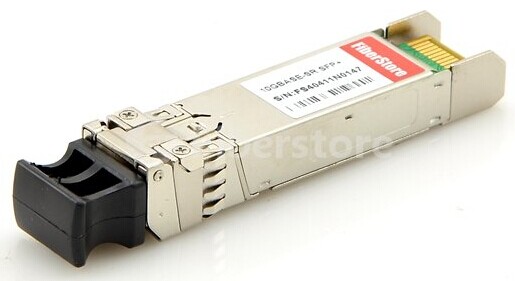
| 10GBASE-SR | 2.6 | 3.1* |
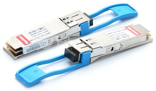
| 40GBASE-SR4 | 1.9 | 1.5 |
| 100GBASE-SR10 | 1.9 | 1.5 |
Factors That Affect The Accuracy of Optical Loss Testing
Optical loss testing of multimode fiber can be affected by many factors, among which there are several major factors that can affect the testing accuracy for optical loss measurements. These include:
1.The type and quality of the “test reference cords”
The type and quality of the “test reference cord” is critical for accurate optical loss measurements in the field. The end-face geometry of the polished ferrule on the cord connector can have a significant effect on the test results and must meet precise parameters such as radius of curvature, apex and fiber protrusion.
The type and quality of the “test reference cord” is critical for accurate optical loss measurements in the field. The end-face geometry of the polished ferrule on the cord connector can have a significant effect on the test results and must meet precise parameters such as radius of curvature, apex and fiber protrusion.
2.Fiber mismatch between the test reference cords and the link under test
Fiber mismatches are the result of inherent fiber characteristics and are independent of the techniques used to join the two optical fibers. The intrinsic coupling loss due to fiber mismatch include core diameter differences, core/cladding concentricity error, numerical aperture differences.
Fiber mismatches are the result of inherent fiber characteristics and are independent of the techniques used to join the two optical fibers. The intrinsic coupling loss due to fiber mismatch include core diameter differences, core/cladding concentricity error, numerical aperture differences.
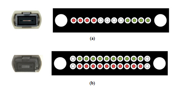
3.The characteristics of light source and how light is coupled into the fiber
The launch conditions and how light is coupled into the fiber can have the greatest effect on optical loss measurements. For multimode fiber, different distributions of launch power (launch conditions) can result in different attenuation measurements.
The launch conditions and how light is coupled into the fiber can have the greatest effect on optical loss measurements. For multimode fiber, different distributions of launch power (launch conditions) can result in different attenuation measurements.
Testing Tools
Various types of testing equipment are available on the market, such as a fiber visual fault locator (VFL), a fiber power meter, a network cable tester or an optical time-domain reflectometer (OTDR).
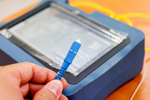
Fiber optic cable testing needs special tools and instruments. And they must be appropriate for the components or cable plants being tested. The following five kinds of fiber testing tools are needed for the testing work.
- OLTS—Optical loss test set (OLTS) with optical ratings matching the specifications of the installed system (fiber type and transmitter wavelength and type) and proper connector adapters. Power meter and source are also needed for testing transmitter and receiver power for the system testing.
- Reference test cable—This cable should be with proper sized fiber and connectors and compatible mating adapters of known good quality. And the connector loss is less than 0.5 dB.
- VFL—Visual fiber tracer or visual fault locator (VFL)
- Microscope—Connector inspection microscope with magnification of 100-200X, video microscopes recommended.
- Cleaning Materials—Cleaning materials intended specifically for the cleaning of fiber optic connectors, such as dry cleaning kits or lint free cleaning wipes and pure alcohol.
Conclusion
Optical loss testing is not as simple as it seems and can be affected by many variables, including fiber mismatch, the type and quality of the test reference cords and the launch conditions (OFL/Mandrel wrap versus Encircled Flux). The more stringent optical loss requirements for high speed applications necessitate an accurate test method for testing links in the field. FS.COM offers a wide selection of fiber testers & tools to fit any fiber optic cable lineman or powerline worker jobs. We stock top high quality test equipment for the communications applications. In the fiber optic installation and maintenance works, Optical Power Meters, Fiber Light Sources, Fiber Scopes and OTDR are commonly used for fiber optic testing. And Splicing fiber tools, termination tool kits and cleaning tools, like strippers, cable cutters, splice protective sleeves help work easier. Besides, high quality fiber cables, such as MPO cable, Push-Pull LC cable and so on are also available for your choice.