Friday, October 30, 2015

HP SFP Transceiver vs Third-Party SFP Transceiver

In order to cut down the costs on the expensive SFP transceiver modules, many users are seeking for a compatible SFP to use. For example, if your network contains HP routers, firewalls, and switches, you might think that only HP SFP branded transceivers will ensure your equipment functions optimally. However, that seemingly reasonable assumption could cost your company thousands of dollars. Compared to the compatible SFP transceiver produced by third-party companies, HP SFP transceiver comes with dramatically inflated price tags while a third-party compatible one is roughly 80 percent less expensive than HP branded SFP transceiver. Although price isn't everything, it's important to know that you're getting your money's worth. That calls for a comparison of what HP SFP transceiver has to offer next to a third-party compatible one.
Performance
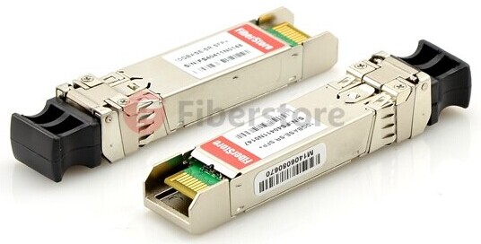
Many people worry that the performance of a third-party compatible SFP is not as good as HP SFP. In fact, HP's own branded SFP transceivers aren't the only ones that work well with their other devices. Compatible third-party SFP transceivers are designed with the specifications of HP technology and function smoothly but have no problem with HP devices such as switches, firewalls, and routers. For example, the following JD092B compatible SFP transceiver provided by Fiberstore offers the same function with HP JD092B and it is fully compatible with HP devices. So you needn’t necessarily buy HP branded SFP transceiver to run your system without glitches or snags.  
JD092B
Failure Rates
Price implies reliability, is it always true? When you pay more for a product, you must expect that higher cost has some added benefits attached. But it is not always the case. Sometimes you're just paying for the brand name. Third-party compatible SFP transceivers often have lower rates of failure than branded HP SFP transceivers, which makes them more reliable but with less money.
Warranty
HP offers a one-year warranty on their branded optical products, plus whatever coverage may be offered under your service contract, for which you must pay separately and these service contracts don't come cheap. But if you have a lot of experience in shopping around, you'll find that many third-party manufacturers of compatible SFP transceivers and resellers even offer significantly better guarantees. It's not hard to find a lifetime warranty for your compatible optical products.
Availability
Time is money. Everyone prefers to get products earlier rather than later. The last thing you concern when trying to construct or upgrade your network is to find out that the SFP transceivers you have paid are on backorder. That kind of situation often happens when you rely on a single brand for the products you need. Expanding your search to a third-party compatible one can make it easier to get your network up and running faster without having to wait for the parts to be restocked.
If you're still hesitant about trying a third-party compatible SFP transceiver, the best way to ensure that you're getting a reliable product at a good deal is to choose a vendor you trust, one with a proven track record of quality products and great customer service. HP compatible SFP transceivers offered by Fiberstore are fully compatible with HP switches & routers. These SFP modules can be mixed and deployed with genuine HP SFP transceivers for seamless network performance and interoperability. We provide a series of HP compatible SFP transceivers as equivalent to J9151A, JD092B, J8177C, J4859B, etc.

Monday, October 12, 2015

Introduction to OTDR

As the use of fiber in premise networks continues to grow, so do the requirements for testing and certifying it. An optical time-domain reflectometer (OTDR) is an electronic-optical instrument used to characterize optical fibers. It locates defects and faults, and determines the amount of signal loss at any point in an optical fiber. This article describes how an OTDR works and the key specifications that should be considered when choosing an OTDR.
How Does an OTDR Work?
An OTDR uses the effects of Rayleigh scattering and Fresnel reflection to measure the characteristics of an optical fiber. By sending a pulse of light into a fiber and measuring the travel time ("time domain") and strength of its reflections ("reflectometer") from points inside the fiber, it produces a characteristic trace, or profile, of the length vs. returned signal level on a display screen. The working principle of OTDR is based on Rayleigh scattering, a small fraction of light spreading in all direction, which is caused when a light pulse encounters the faults and heterogeneity in optical fiber. (as shown in the following picture.)
OTDR
OTDR Selection Guide
When choosing an OTDR, it is important to select the specific OTDR performance and features according to the required specifications listed below.
    • Dynamic Range
The dynamic range of an OTDR determines how long of a fiber can be measured. The total optical loss that an OTDR can analyze is mainly determined by the dynamic range. The dynamic range affects the accuracy of the link loss, attenuation and far-end connector losses. Thus, having sufficient dynamic range is really important. The manufacturers specify dynamic range in different way. The higher the dynamic range, the longer the distance an OTDR can analyze.
    • Dead Zones
Dead zone refers to the space on a fiber trace following a Fresnel reflection in which the high return level of the reflection covers up the lower level of backscatter. To specify an OTDR's performance, it is important to analyze the dead zone and ensure the whole link is measured. Dead zones are characterized as an event dead zone and an attenuation dead zone. Event dead zone refers to the minimum distance required for consecutive reflective events to be "resolved" (for example, to be differentiated from each other). Attenuation dead zone refers to the minimum distance required, after a reflective event, for the OTDR to measure a reflective or non-reflective event loss.
    • Resolution
There are two resolution specifications: loss (level), and spatial (distance). Loss resolution is the ability of the sensor to distinguish between levels of power it receives. When the laser pulse gets farther out in the fiber, the corresponding backscatter signal gets weaker and the difference between backscatter levels from two adjacent measurement points becomes larger. Spatial resolution is how close the individual data points that make up a trace are spaced in time (and corresponding distance). The OTDR controller samples the sensor at regular time intervals to get the data points. If it takes readings from the sensor very frequently, then the data points will be spaced close together and the OTDR can detect events in the fiber that are closely spaced.
    • Pass/Fail Thresholds
This is an important feature because a great deal of time can be saved in the analysis of OTDR traces if the user is able to set pass/fail thresholds for parameters of interest (such as splice loss or connector reflection). These thresholds highlight parameters that have exceeded a warning or fail limit set by the user and, when used in conjunction with reporting software, it can rapidly provide re-work sheets for installation/commissioning engineers.
    • Post-Processing and Reporting
Report generation could be another major time saver. For example, some OTDRs with specialized post-processing software allow fast and easy report generation, which might reduce the post-processing time up to 90 percent. These reports also include bidirectional analyses of OTDR traces and summary reports for high-fiber-count cables.
  • Your Applications and Users
Some OTDRs are designed to test long distance optical fibers and some others to test short distance optical fibers. For example, if you are to test premises fiber networks where short distance optical fibers are installed, OTDRs designed for testing long distance optical fibers are not suitable. Besides, knowing your users and the time it will cost is also necessary. Because some types of OTDRs are easy to use and some others are complicated to set up.
When selecting an OTDR, you're supposed to take all the above factors into consideration. Fiberstore supplies a wide range of OTDRs available with various fiber types and wavelengths (including single-mode fiber, multi-mode fiber, 1310nm, 1550 nm, 1625 nm, etc). They also supply OTDRs of famous brands, such as JDSU MTS series, EXFO FTB series, YOKOGAWA AQ series and so on. OEM portable and handheld OTDRs are available as well.

Thursday, October 8, 2015

Link Budget Evaluation Over SMF and MMF

Evaluating a link budget is equivalent to calculating the total loss suffered by a transmitted signal along fiber channels with the minimum receiver power to maintain normal operation. Calculating the link budget helps network architects to identify the feasibility of a physical-layer deployment.
Optical fibers come in several different configurations, each ideally suited to a different use or application. Early fiber designs that are still used today include single-mode fiber (SMF) and multimode fiber (MMF). And the most common optical communication data links include point-to-point transmission, WDM and amplified transmission. This article depicts the rules to be applied in order to evaluate link budget of these optical transmissions over SMF and MMF.
Link Budget for Point-to-Point Transmissions over Multimode Fibers
In this first case, the rule is fairly simple. A few parameters need to be taken into account:
● The minimum transmit power guaranteed (minTx), expressed in dB/m
● The minimum receive power required (minRx), expressed in dB/m
● The loss of optical connectors and adapters (L), expressed in dB
● The number of connectors and adapters (n)
● The normalized fiber loss (FL), expressed in dB/km
● The reach or distance to be achieved (d), expressed in km
With these parameters, the link budget (LB) expressed in dB is given as follows:
● (LB) = (minTx) – (minRx)
This value needs to be compared to the total loss (TL) suffered by the transmitted signal along the given link, and expressed in dB:
● (TL) = n*(L) + d*(FL)
If LB is greater than TL, then the physical deployment is theoretically possible.
In these calculations n is at least equal to 2 since there are a minimum of 2 connectors at each end, L is typically around 0.5 to 1 dB, and FL is of about 1 to 1.5 dB per km.
Link Budget for Point-to-Point Transmissions over Single-mode Fibers
At first, you need to know that the lasers deployed in optical communications typically operate at or around 850 nm (first window), 1310 nm (second window), and 1550 nm (third and fourth windows). In this second case, the calculations are exactly similar to the previous case. Only the numerical values will differ. For single-mode point-to-point transmissions, n is at least equal to 2, L is typically around 0.3 to 0.5 dB, and FL is of about 0.4 dB per km in the second window and about 0.25 dB per km in the third window.
The following drawings show the power budget of a 2km hybrid multimode/singlemode link with 5 connections (2 connectors at each end and 3 connections at patch panels in the link) and one splice in the middle.
power budget
Link Budget for WDM and Amplified Transmissions over Single-mode Fibers
In the case of WDM transmissions, passive modules are used to multiplex and demultiplex various wavelengths respectively before and after the signal propagates along the fiber channel. These passive modules introduce additional insertion losses suffered by the signal transmitted.
Additionally, the signal may be amplified and compensated for dispersion, and in this case, the amplifier gain and the dispersion compensation unit's loss need to be taken into account. Dispersion and OSNR (optical signal over noise ratio) penalties suffered by the receiver shall be considered as well.
Therefore all the parameters needed for a proper link budget evaluation are:
● The minimum transmit power guaranteed (minTx), expressed in dB/m
● The minimum receive power required (minRx), expressed in dB/m
● The loss of optical connectors and adapters (L), expressed in dB
● The number of connectors and adapters (n)
● The normalized fiber loss (FL), expressed in dB/km
● The reach or distance to be achieved (d), expressed in km
● The loss of passive add/drop modules (A and D), expressed in dB
● The gain of the amplifier (G), expressed in dB
● The penalty suffered by the receiver (P), expressed in dB
● The loss of a dispersion compensation unit (DCU), expressed in dB With these parameters, (LB) is given as for previous cases:
● (LB) = (minTx) – (minRx)
And the total loss is expressed as follows:
● (TL) = n*(L) + d*(FL) + (A) + (D) – (G) + (DCU) + (P)
Here again, if LB is greater than TL, then the physical deployment is feasible. Please note that for simplicity, only one amplifier, one dispersion compensation unit, and one set of add/drop modules are considered in this example. If more devices are planned to be deployed, their loss or gain should be added or subtracted accordingly in order to calculate TL.
Link budget is a way of quantifying the link performance. And the performance of any communication link depends on the quality of the equipment being used. Thus, when evaluating a link budget, you are supposed to consider the types of applications, the reach to be achieved, as well as the types of optical fibers deployed. For more information about fiber optical link products, please visit FS.COM.