Parallel optics is a term representing both a type of optical communication and the devices on either end of the link that transmit and receive information. Compared with traditional optical communication, parallel optical communication employs a different cabling structure for signal transmitting aiming at high-data transmission for short reach multimode fibers that are less than 300 meters. Traditional fiber optic transceivers cannot satisfy the increasing demand for high speed transmission, like 40GbE, while parallel optics technology can be a cost effective solution for 40/100GbE transmission.
Comparison between parallel optics technology and the traditional serial optical communication would better explain what parallel optics is and the reason why it is a cost effective solution to high data rate transmission. The following of this article will offer the comparison between the two optical communication technology from two aspects: connectivity method and key components.
Connectivity Method
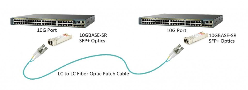
Literally, parallel optics and serial optics transmit signals in different ways. In traditional serial optical communication, on each end of the link, there are one transmitter and one receiver. For example, the transmitter on End A communicates to the receiver on End B, sending a single stream of data over a single optical fiber. And a separate fiber is connected between the transmitter on End B and the receiver on End A. In this way, a duplex channel is achieved by two fibers.
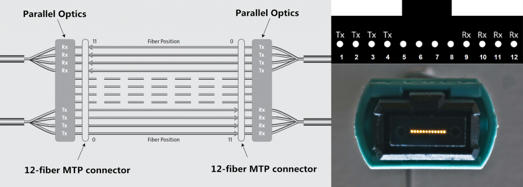
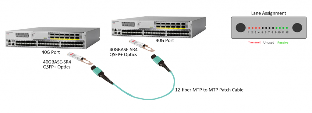
While in parallel optical communication, duplex transmission is achieved in a different way. A signal is transmitted and received through multiple paths, thus, the parallel optical communication can support higher data rate than the traditional optical communication. This is because, the devices for parallel optic communication on either end of the link contain multiple transmitters and receivers. For instance, in 2010 IEEE 802.3ba approved the 40GBASE-SR4 physical-medium-dependent multimode parallel optical solution, which uses eight fibers to transmit four duplex channels each at 10 Gigabit Ethernet. In this case, four 10Gbps transmitters on End A communicate with four 10Gbps receivers on End B, spreading a single stream of data over four optical fibers at a total data rate of 40Gbps.
Key Components
The parallel optical communication transmitting signals over multiple fibers, which has great advantages over traditional serial optical communication. It also means that it requires different components to support its high data rate transmission.
Connector — As previously mentioned, duplex transmission in serial optical communication uses 2-fiber duplex connectors, like duplex LC connectors to link the optics with other devices, while in parallel optical communication, multi-fibers are used to reach a higher data rate. Thus, multi-fiber connectors, like 12-fiber MPO connectors are used to connect with other devices. MPO connector is one key technology support parallel optical communication. This connectivity method is showed in the following picture (Tx stands for transmit; Rx stands for receive).

Optical transceiver light source — Another complementary technology for parallel transmission is the light source of parallel optics—VCSELs (Vertical Cavity Surface Emission Lasers). Comparing with the edge-emitting semiconductor lasers in the traditional optics, VCSELs have better formed optical output which enables them to couple that energy into optical fibers more efficiently. In addition, VCSELs emit from the top surface, they may be tested while they are part of a large production batch (wafer), before they are cut into individual devices, which dramatically lowers the cost of the lasers. The following chart is about the comparison between VCSELs and edge-emitting semiconductor lasers. Cheaper to manufacture, easier to test, less electrical current required, supporting higher data rate, parallel optics using VCSELs could be a better choice to reach 40/100GbE transmission compared with traditional serial optics.
Parallel Optics for 40/100GbE Transmission
IEEE has already included physical layer specifications and management parameters for 40Gbps and 100Gbps operation over fiber optic cable. Two popular parallel optics solutions for 40Gbps and 100Gbps over multimode fibers are introduced here. For 40G, 40GBASE-SR4 transceiver is usually used, which requires a minimum of eight OM3/OM4 fibers for a transmit and receive link (4 fibers for Tx and 4 fibers for Rx). 100GBASE-SR4 transceiver (eg. QSFP-100G-SR4) is for 100Gbps transmission, which works through 4x25Gb/s 850nm VCSEL-based transmitter to achieve maximum link length of 100m on OM4 multimode fiber.
Conclusion
Parallel optical communication uses multiple paths to transmit a signal at a greater data rate than the individual electronics can support. Parallel transmission can either lower the cost of a given data rate (by using slower, less expensive optoelectronics) or enable data rates that are unattainable with traditional serial transmission. The capabilities and uses of parallel optics and MPO technology continue to evolve and take shape as higher-speed fiber optic transmission, including 40/100GbE. It is uncertain that parallel optical communication would be the trend in the future.


