Friday, March 17, 2017

DWDM Solutions for Arista 7500E Series Switches

Nowadays, the deployment of DWDM solution has been hotly debated in many enterprise networks, especially in the new Lay2 and Lay3 equipment like Arista 7500E series switches. For many enterprises, DWDM network solutions are undoubtedly the best choices of action, because they can provide a scalable and elastic solution for the enterprise that offered high bandwidth and data separation. This article will demonstrate DWDM solutions to Arista 7500E switches which are the foundation of two-tier open networking solutions for cloud data centers.
Analysis of DWDM System
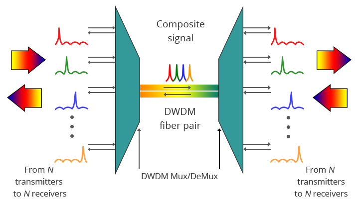
DWDM (Dense Wavelength Division Multiplexing) is a technology allowing high throughput capacity over longer distances commonly ranging between 44-88 channels and transferring data rates from 100 Mbps up to 100 Gbps per wavelength. For intra-datacenter solutions, an endpoint connection often uses multimode (850 nm) for short ranges and single mode (1310 nm) for longer ranges. The DWDM node converts this local connection to a channelized frequency or wavelength, which is then multiplexed with other wavelength and transmitted over a single fiber connection.
A key advantage of DWDM is that it’s bitrate independent. DWDM-based networks can transmit data in IP, ATM, SONET, SDH and Ethernet. Therefore, DWDM systems can carry different types of traffic at different speeds over an optical channel. Voice transmission, email, video and multimedia data are just some examples of services which can be simultaneously transmitted in DWDM systems.
DWDM multi-channel Mux/Demux
Arista 7500E 100G DWDM Line Card
With full support for Layer2 and Layer3 protocols, Arista 7500E series switch is the ideal option for the network spine for two tier data centers applications. Arista 7500E especially provides the perfect resolution for high bandwidth Metro and long-haul DCI solutions with the 6-port DWDM line card. It has great advantage to migrate from existing 10G DWDM to 100G coherent line side modules. The 7500E series DWDM line card provides six 100G ports with coherent 100G tunable optics, which enables customers to connect directly into existing WDM MUX module without the need to add transceivers, which can save cost and space to a large extent. The coherent optics use C-band region wavelengths and offer a cost efficient solution for up to 96 channels of 100Gb over a single dark fiber pair.
Use Cases for Arista 7500E DWDM Card
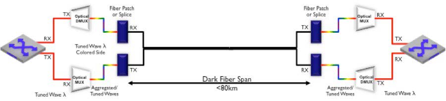
    • Less Than 80 km Dark Fiber Connection
      For distance less than 80 km, Arista 7500E switch with DWDM line cards can directly terminate a dark fiber connection with a pair of passive DWDM Mux, thus achieving a point-to-point connection between two locations.
Dark Fiber Connection
  • Between 80 km and 150 km Connection
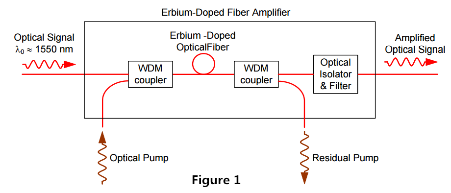
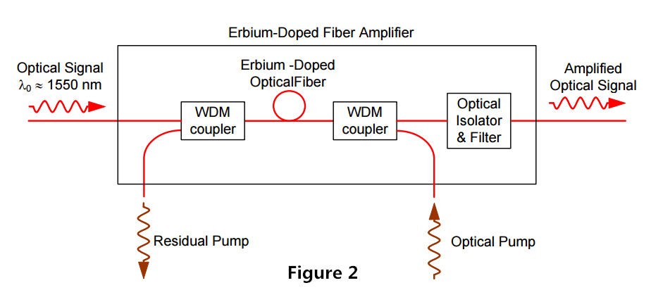
    For distance greater than 80 km but less than 150 km, losses occurred during the process of transmission should be considered. In order to boost the power level, an EDFA (Erbium Doped Fiber Amplifier) is used to gain flatness, noise level, and output power, which is typically capable of gains of 30 dB or more and output power of +17 dB or more. With the use of EDFA, the signal can be boosted into a certain power level, thus achieving distances of up to 150 km.
Conclusion
The Arista 7500E series DWDM solution offers a cost-effective solution for transporting scalable and massive volumes of traffic, and enhances the 7500E system by providing high performance 100G DWDM port density with the same rich features and dedicated secure encryption in compact and power-efficient systems. Enterprises can easily migrate existing metro and long-haul DWDM networks to add new 100G capacities, thus expanding Layer2 and Layer3 services.
Originally published at http://www.china-cable-suppliers.com/dwdm-solutions-arista-7500e-series-switches.html

Thursday, March 9, 2017

Using EDFA Amplifier for Long-Haul CATV Systems

With Laser technology combining with fiber optic technology, CATV systems in the field of optical communication have demonstrated unprecedented and irreplaceable achievements in the past few decades. When transmitting optical signals with fibers, fiber attenuation is the main factor that limits the transmission distance. EDFA (Erbium-Doped Fiber Amplifier) designed for CATV long-haul transmission avoids the conversion of optic-electric-optic in CATV long-haul transmission. It amplifies low signal power into high signal power, thus extending transmission distance. This post analyzes EDFA configurations and the utilization in long-haul CATV systems.
EDFA Leading Position in CATV Systems
EDFA is one of the most prominent achievements in fiber optic transmission technology over the past decade. Because it cleverly combined the laser technology and optical fiber manufacturing technology in the CATV systems and its applications were then rapidly expanded. Originally PDFA and EDFA amplifiers were equally used for CATV systems, but today, EDFA has completely replaced PDFA and become the primary device for fiber optic transmission systems. Why EDFA has leading position on CATV systems? Because EDFA noise and distortion characteristics are better, and its superior characteristics can be clearly seen in the following:
  • Operates at wavelength of 1550nm, consistent with C-band where fiber has the lowest loss
  • Has higher saturation output power, useful in systems requiring transmission up to 100 km or systems requiring the optical signal to be split to multiple fiber optic receivers
  • The signal gain spectrum is wide up to 30nm or more, can be used for broadband signal amplification, especially for WDM (wavelength division multiplexing) system, ideal for radio and data services networks
  • Has user friendly interface RS232, easy to control and monitor with computers
  • Low noise figure with high stability
EDFA Configurations
The configuration of a co-propagating EDFA is shown in Figure 1. The optical pump is combined with the optical signal into the erbium-doped fiber with a wavelength division multiplexer. A second multiplexer removes residual pump light from the fiber. An in-line optical filter provides additional insurance that pump light does not reach the output of the optical amplifier. An optical isolator is used to prevent reflected light from other portions of the optical system from entering the amplifier.
EDFA Configuration-1
An EDFA with a counter propagating pump is pictured in Figure 2. The copropagating geometry produces an amplifier with less noise and less output power. The counter propagating geometry produces a noisier amplifier with high output power. A compromise can be made by combining the co- and counter-propagating geometries in a bi-directional configuration.
EDFA Configuration-2
A Typical CATV System Using EDFA
Figure 3 illustrates a basic long-haul CATV transmission system designed to carry 77 channels of CATV signals for 100 km in a basic point-to-point configuration.
CATV EDFA
As you can see in Figure 3, the local CATV provider sends 77 channels of CATV signals at the transmitting side. After processing and RF combining, those multiple signals are combined into one channel of CATV signal with the wavelengths of 1550 nm. It transmits over a single-mode optical fiber to 50 km. An EDFA amplifier is used at the middle point to amplify the signals to a certain power level, continuing to transmit over a single mode fiber to 100 km. At the receiving side, the 1550nm CATV channel is split into multiple channels of 1550nm CATV signals, serving multiple hotel cable TV users.
FS.COM CATV EDFA Optical Amplifiers List
EDFA has undoubtedly received wide interest for CATV applications because of its high output power, low distortion and low noise capability. FS.COM supplies optical amplifiers including CATV EDFA, SDH EDFA, DWDM amplifier, etc. The following table lists FS.COM CATV EDFA amplifiers which are available with range of output power from 13 dBm to 24 dBm to meet the requirements of a high-density solution for the large-scale distribution of broadband CATV video and data signals to video overlay receivers in a FTTH/FTTP or PON system.
image


Sunday, February 26, 2017

Evolution of Optical Wavelength Bands

As fiber optic networks have developed for higher speeds, longer distances, and wavelength-division multiplexing (WDM), fibers have been used in new wavelength ranges, namely "bands". Fiber transmission bands have been defined and standardized, from the original O-band to the U/XL-bands. This article will mainly illustrate the evolution of the typical fiber transmission bands used for different optical telecom systems.
Among these bands, the O-band, also called the Original-band, was the first band used in optical telecommunication because of the small pulse broadening (small dispersion); Single-mode fiber transmission began in the "O-band" just above the cutoff wavelength of the SM fiber developed to take advantage of the lower loss of the glass fiber at longer wavelengths and availability of 1310nm diode lasers.
DWDM
The E-band represents the water peak region while the U/XL-band resides at the very end of the transmission window for silica glass. The E-band (water-peak band) has not yet proven useful except for CWDM. It is probably mostly used as an extension of the O-band but few applications have been proposed and it is very energy-intensive for manufacture. The E-band and U/XL-bands usually are avoided because they correspond to high transmission loss regions.
To take advantage of the lower loss at wavelength of 1550nm, fiber was then developed for the C-band. The C-band is commonly used along with the development of ultra-long distance transmission with EDFA and WDM technologies. As transmission distances became longer and fiber amplifiers began being used instead of optical-to-electronic-to-optical repeaters, the C-band became more important. With the advent of DWDM (dense wavelength-division multiplexing) which enables multiple signals to share a single fiber, the use of C-band was expanded.
With the development of fiber amplifiers (Raman and thullium-doped), DWDM system was expanded upward to the L-band, leveraging the wavelengths with the lowest attenuation rates in glass fiber as well as the possibility of optical amplification. Erbium-doped fiber amplifiers (EDFAs, which work at these wavelengths) are a key enabling technology for these systems. Because WDM systems use multiple wavelengths simultaneously, which may lead to much attenuation. Therefore optical amplification technology is introduced.
Despite great expectations, the number of installed systems using all-Raman solutions worldwide can be counted on one hand. In the future, however, the L-band will also prove to be useful. Because EDFAs are less efficient in the L-band, the use of Raman amplification technology will be re-addressed, with related pumping wavelengths close to 1485nm.
Although CWDM is now considered as a low-cost version of WDM that has been in use, most do not work over long distances. The most popular is FTTH PON system, sending signals downstream to users at 1490nm (in S-band) and using low cost 1310nm transmission upstream. Early PON systems also use 1550 downstream for TV, but that is being replaced by IPTV on the downstream digital signal at 1490nm. Other systems use a combination of S, C and L bands to carry signals because of the lower attenuation of fibers. Some systems even use lasers at 20nm spacing over the complete range of 1260nm to 1660nm but only with low water peak fibers.
Although various wavelength bands of the O-, S-, C- and L- bands have come into use with the explosive expansion of the traffic in recent years, the optical fiber amplifiers for the O- and S-band wavelengths were not realized for many years because of many technical hurdles. C- and L-band most commonly used in fiber optic networks will play more and more important roles in optical transmission system with the growth of FTTH applications.
Originally published at http://www.china-cable-suppliers.com

Wednesday, February 22, 2017

Installation Guide to CWDM MUX/DEMUX System

CWDM MUX/DEMUX System Overview
Coarse Wavelength Division Multiplexing (CWDM) is a wavelength multiplexing technology for access networks. It is designed to increase fiber optic network capacity without adding additional fibers. The wavelengths of CWDM channels range from 1270nm to 1610nm with 20nm spacing, which allows the use of cost-effective lasers. CWDM MUX/DEMUX system is a passive, optical solution to increase the flexibility and capacity of existing fiber lines in high-speed networks. By adding more channels into available fibers, the CWDM MUX/DEMUX system enables greater versatility for data communications in ring, point-to-point, and multipoint topologies for both enterprise and metro applications.
CWDM MUX/DEMUX System Components
All CWDM system components are passive and require no power supplies. They consist of the rack mount chassis, a set of CWDM MUX/DEMUX and CWDM OADM (Optical Add/Drop Multiplexing) modules with color-coded ports. The CWDM MUX/DEMUX takes 4 or 8 different wavelength channels and multiplexes them onto one common fiber cable for transmission to the network. Then it demultiplexes the channels it receives from the network and sends each channel to a different device. Multiple modules may be chained through the expansion port on the four-channel modules. Thus it increases flexibility and enables growth for evolving networks.
The CWDM OADM module can add or drop CWDM channels into an existing backbone ring. It provides the ability to drop one CWDM channel from the network fiber, while allowing all other channels to continue pass to other nodes. Similarly, the drop/insert module removes an individual channel from the network fiber, however, it also provides the ability to add that same channel back onto the network fiber. The drop/insert module supports two paths (east and west) for dropping and adding, so that network viability is maintained in a ring topology, even if a break occurs in the ring.
CWDM MUX/DEMUX System Installation Guide
Step1: Mount the system chassis on the rack. The CWDM rack-mount chassis can be mounted in a standard 19-inch cabinet or rack. Make sure that you install the rack-mount chassis in the same rack or an adjacent rack to your system so that you can connect all the cables between your CWDM MUX/DEMUX modules and the CWDM SFP transceivers.
mounting-system-chassis
Step2: Install the CWDM MUX/DEMUX modules. First loose the captive screws on the blank of module panel and remove the panel. Then align the module with the slot of the chassis shelf and gently push the module into the slot. Finally, ensure that you line up the captive screws on the module with the screw holes on the shelf and tighten them up.
installing-CWDM-MuxDemux-modules
Step3: Install CWDM SFP transceivers. Since each channel has a specific wavelength, transceivers must comply with the right wavelengths. Each wavelength must not appear more than once in the system. Device pairs must carry transceivers with the same wavelength.
Step4: Install the CWDM MUX/DEMUX to the switch. After inserting the CWDM SFP transceiver into the switch, single-mode patch cables are used to connect the transceiver to the CWDM MUX/DEMUX module.
Connect-the-CWDM-Mux-Demux-to-Switch
Step5: Connect the CWDM MUX/DEMUX pairs. In a CWDM MUX/DEMUX system, multiplexer and demultiplexer must work in pairs. Two strands of single-mode patch cables are needed in the duplex MUX/DEMUX module and one strand for the simplex one. Simply insert single-mode cables from your system equipment to the appropriate port on the CWDM MUX/DEMUX or OADM module.
Conclusion
CWDM MUX/DEMUX system is an attractive solution for carriers who need to upgrade their networks to accommodate current or future traffic needs while minimizing the use of valuable fiber strands. With CWDM technology, you can accommodate Ethernet and SONET on a single fiber that enables converged circuit/packet networks at high demand access sites. Besides, CWDM MUX/DEMUX can work seamlessly with transceivers to optimize link length, signal integrity and network cost, thus becoming a single rack-mount solution for enhanced design, power and space efficiency.